Wiring with the display system
254
1SVC 440 795 M1100
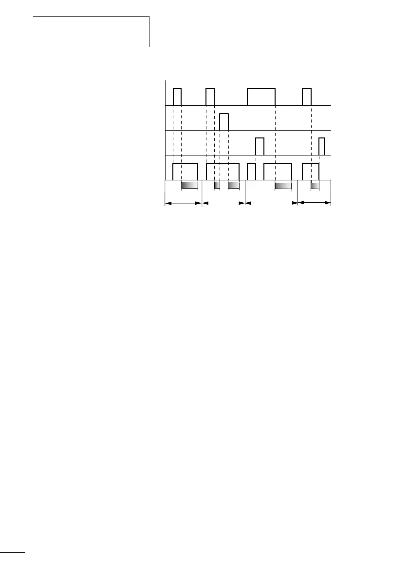
Figure: 133: Signal diagram of timing relay, off-delayed
(with/without random switching, with/without
retriggering)
1: Trigger coil T…EN
2: Stop coil T…ST
3: Reset coil T…RE
4: Switching contact (N/O contact) T…Q1
t
s
: Setpoint time
•Range A:
The time elapses after the trigger coil is deactivated.
•Range B:
The stop coil stops the time from elapsing.
•Range C:
The reset coil resets the relay and the contact. After the reset coil
drops out, the relay continues to work normally.
•Range D:
The reset coil resets the relay and the contact when the function
block is timing out.
A
B
t
1
+ t
2
= t
s
t
s
C
1
2
4
3
t
s
D
t

 Loading...


