Visualization with the
display system
312
1SVC 440 795 M1100
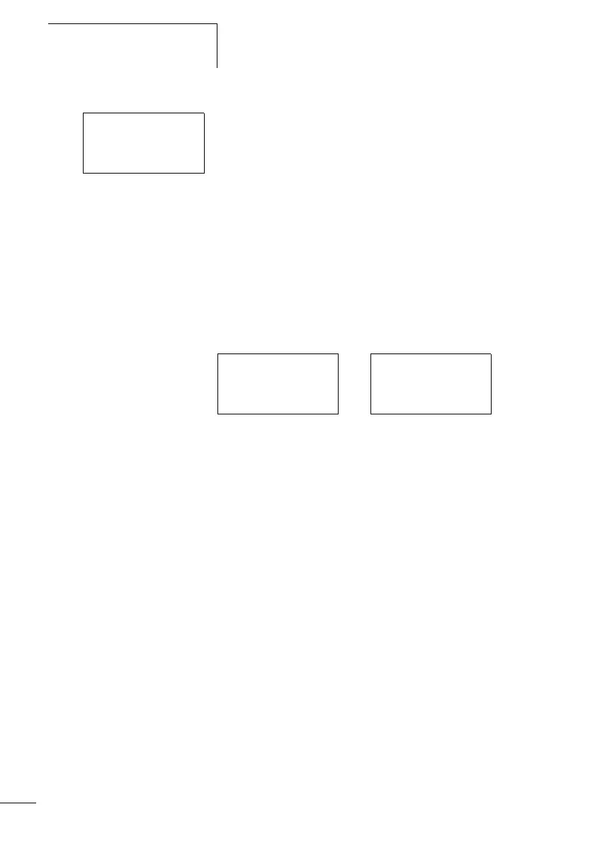
Screen 1:
The first screen shows four bit message text elements. These
are triggered in succession via the outputs Q1 to Q4 and
appear in the display.
Screen 2:
The second screen contains a message text element with
two message texts. In all screens the message texts are
activated via the counter values “1” and “2”. When the
timing relays are reset by T06, counter C01 is activated
which reaches the status value 1, and the “Error” message
appears. It flashes as specified in the Display change tab
where the FB parameter is set to <= 1. If the status value of
CO1 is 2, RESTART is displayed.
Figure: 176: Message text as status indication
Start Machine 1
Start Machine 2
Start Machine 3
Start Machine 4
Error RESTART

 Loading...


