Installation
44
1SVC 440 795 M1100
X Slightly push the display system down and against the
top-hat rail until it also snaps onto the top lip of the top-hat
rail. Slightly push the device down and against the top-hat
rail until it also snaps onto the bottom lip of the rail.
The display system will clip into place automatically.
X Check that the device is seated firmly.
The device is mounted vertically on a top-hat rail in the same
way.
Screw mounting
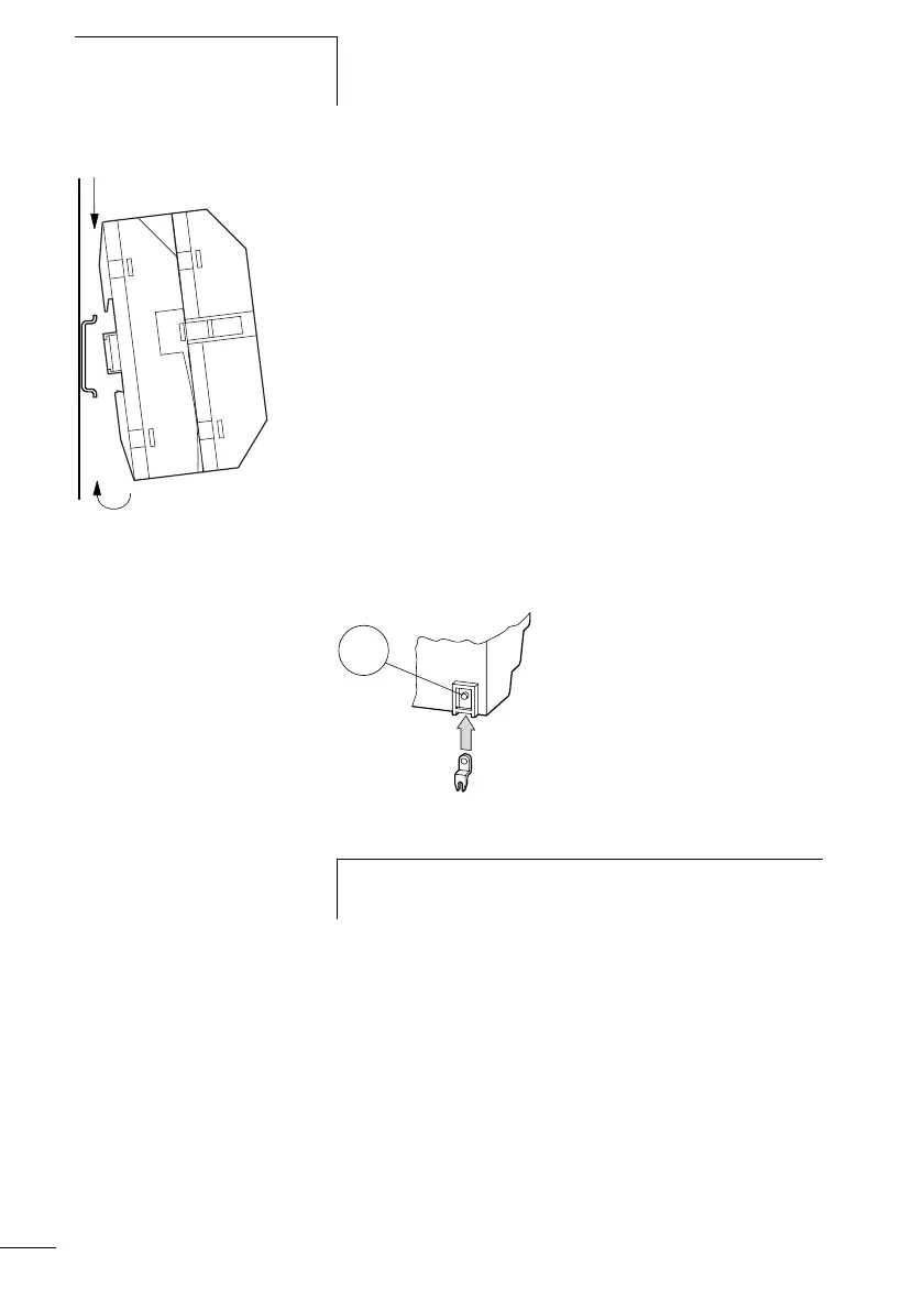
Fixing brackets that can be inserted on the rear of the display
system are required for screw mounting. The fixing brackets
are available as an accessory. The display base module can
be screw fastened without the display module.
Figure: 25: Inserting a fixing bracket
-
CLICK !
h
Three fixing brackets are sufficient for a device with four
fixing points.