EasyManuals Logo

ABB CL Series User Manual

ABB CL Series
428 pages
To Next Page IconTo Next Page
To Previous Page IconTo Previous Page
Page #75 background imageLoading...
Page #75 background image
Installation
72
1SVC 440 795 M1100
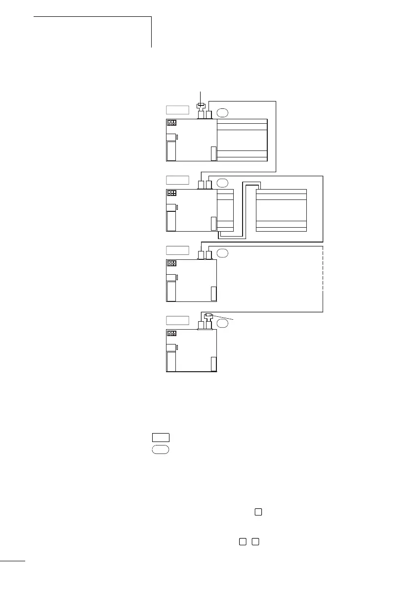
Figure: 56: Bus terminating resistors
a First station on the CL-NET network
b Bus terminating resistor CL-LAD.TK009
c Last station on the CL-NET network
Physical location, place
Station number
Both RJ45 interfaces are visible after the cover plate has
been removed.
When a cable is plugged in, the mechanical connection must
be audible (click) and visible .
Before a plug or cable is removed, the mechanical locking
feature must be undone , .
1
1
2
2
3
3
8
8
R 1 - 12
S 1 - 6
R 1 - 12
S 1 - 8
a
c
b
b
CL-LDC.LN...
CL-LDC.LN...
CL-LDC.LN...
CL-LDC.LN...
1
2 3

Table of Contents

Questions and Answers:

Question and Answer IconNeed help?

Do you have a question about the ABB CL Series and is the answer not in the manual?

ABB CL Series Specifications

General IconGeneral
ManufacturerABB
Rated Control Supply Voltage (Us)24 V DC
MountingDIN Rail
CategoryRelays
Contact ConfigurationSPDT
Coil Voltage24 V DC
Operating Temperature-40°C to +70°C
Electrical Life100 Thousand Cycles
OutputRelay

Related product manuals