6 Mounting system equipment
SPC Controllers should be installed in restricted access areas only. A restricted access area is an area
accessible only to skilled persons and to instructed persons with the proper authorization.
This chapter covers:
6.1 Mounting a G2 housing 23
6.2 Mounting a G3 housing 23
6.3 Mounting a keypad 28
6.4 Mounting an expander 28
6.5 Wiring the X-BUS Interface 28
6.1 Mounting a G2 housing
The SPC G2 housing is supplied with a metallic c cover. The cover is attached to the base of the housing
by 2 securing screws located on the top and bottom of the front cover.
To open the housing, remove both screws with the appropriate screwdriver and lift the cover directly
from the base.
The G2 housing contains the controller PCB (Printed Circuit Board) mounted on 4 support pillars. An
optional input/output module can be mounted directly beneath the controller PCB. A battery with
capacity of 7Ah max. can be accommodated below the controller.
An optional external antenna must be fitted to housings with metallic lid if the wireless functionality is
required. If an antenna is fitted to the unit, it must be enabled in the firmware.
The SPC G2 housing provides 3 screw holes for wall mounting the unit.
To wall mount the housing, remove the cover and locate the initial fixing screw hole at the top of the
housing. Mark the position of this screw hole on the desired location on the wall and drill the initial screw
hole. Screw the unit to the wall and mark the position of the bottom 2 screw hole positions with the unit
vertically aligned.
Screws with a 4–5mm shank, a minimum head diameter of 8mm and a minimum length of 40mm are
recommended for mounting the housing. Additional expansion plugs or fixings may be required
depending on the construction of the wall.
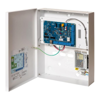
6.2 Mounting a G3 housing
The SPC G3 housing is supplied with a metallic front cover. The cover is attached to the base of the
housing by hinges and secured with one screw on the right hand side of the front cover.
To open the housing, remove the screws with the appropriate screwdriver and open the front cover.
The G3 housing contains the controller PCB (Printed Circuit Board) mounted on a hinged mounting
bracket. Expanders and PSUs can be mounted on the underside of the hinged mounting bracket and
also on the back wall of the housing underneath the mounting bracket.
An optional external antenna must be fitted to housings with metallic lid if the wireless functionality is
required. If an antenna is fitted to the unit, it must be enabled in the firmware.
The SPC G3 housing provides 3 screw holes for wall mounting the unit (see item 1 below).
Screws with a 4–5mm shank, a minimum head diameter of 8mm and a minimum length of 40mm are
recommended for mounting the housing. Additional expansion plugs or fixings may be required
depending on the construction of the wall.
© Vanderbilt 2023 23 I-200572
08.12.2023