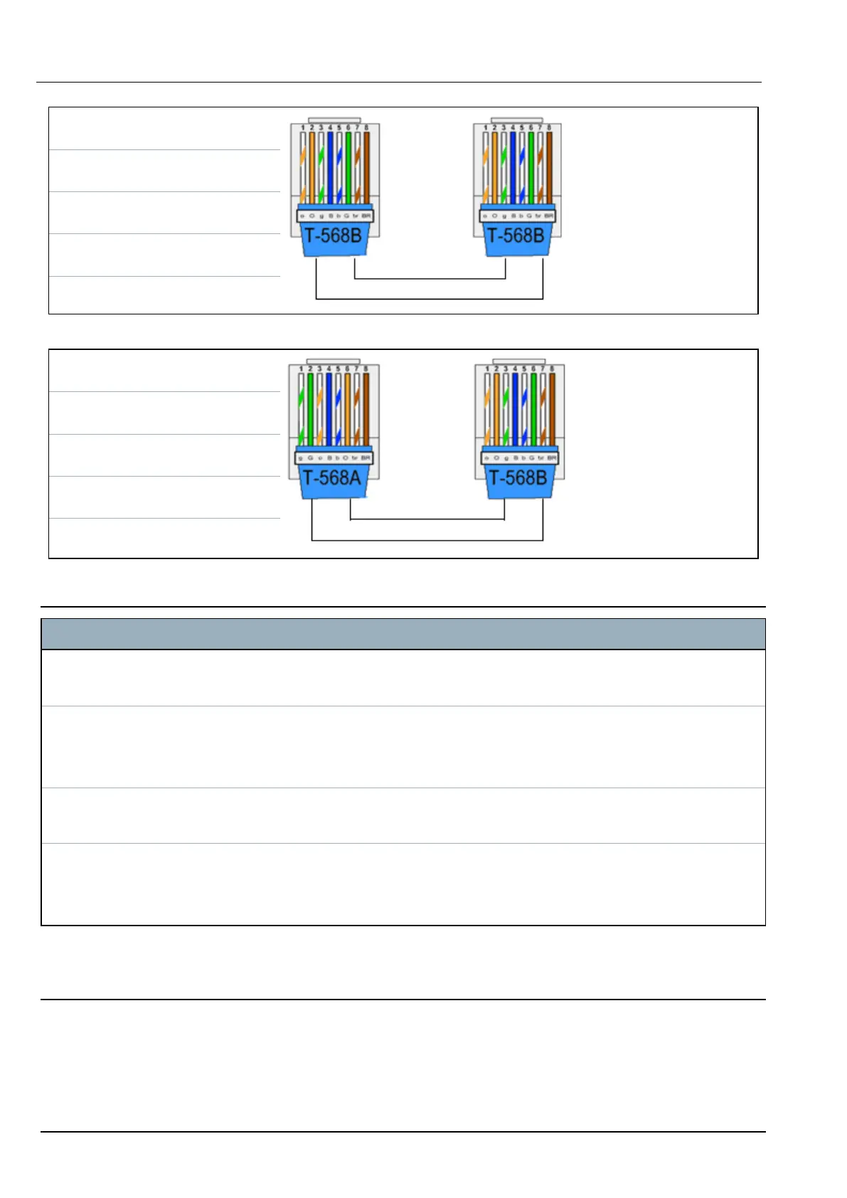
RJ45 PIN RJ45 PIN
1 (RX +) 1 (TX +)
2 (RX -) 2 (TX -)
3 (TX+) 3 (RX+)
6 (TX-) 6 (RX-)
Use the crossover cable for connecting the SPC controller directly to a PC.
RJ45 PIN RJ45 PIN
1 (RX +) 3 (TX+)
2 (RX -) 6 (TX-)
3 (TX+) 1 (RX +)
6 (TX-) 2 (RX -)
21.2 Controller status LEDs
LED Function
LED 1 Main Processor Heartbeat
FLASHING: system is functioning normally
LED 2 System Fault
ON: A hardware fault has been detected on the board.
OFF: No hardware fault has been detected.
LED 3 Secondary (Coprocessor) Heartbeat
FLASHING: System is functioning normally.
LED 4 Mains Supply
ON: Mains failure
OFF: Mains OK
21.3 Powering expanders from the auxiliary power terminals
To calculate the number of expanders/keypads that can safely be powered from the auxiliary 12V DC
power terminals, add the total maximum current draw from all of the expanders/keypads to be powered
and determine if this total is less than the specified 12V DC auxiliary power.
SPC42/52/53/63 – Installation & Configuration Manual Appendix
© Vanderbilt 2023 265 I-200572
08.12.2023