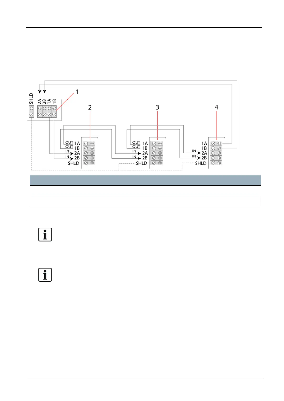
The loop (or ring) cabling method offers the highest security by providing fault tolerant
communications on the X-BUS. All keypads and expanders are supervised and in case of a X-BUS
fault or break, the system continues to operate and all detectors are monitored. This is achieved by
connecting 1A, 1B on the controller to 2A, 2B on the first keypad or expander. The wiring continues
with connection 1A, 1B to 2A, 2B on the next expander etc. to the last keypad or expander. The last
connection is 1A, 1B of the last expander to 2A, 2B of the controller. See wiring configuration in the
figure below.
Number Description
1 Controller
2-4 Expanders
9.1.2 Spur configuration
NOTICE: SPC42, SPC52, SPC53, SPC63 support 2 spurs (2 X-BUS ports).
NOTICE: All expanders/keypads are fitted with a termination jumper by default. In spur
configuration it is imperative to have these jumpers fitted.
The spur (or open loop) cabling method offers a high level of fault tolerance and may be more
convenient on certain installations. In the case of a X-BUS fault or break, all expanders and detectors
up to the fault continue to be supervised.
In this configuration, the SPC controller uses a single the X-BUS port (1A/1B or 2A/2B) to support a
group of expanders. See wiring configuration in the figure below. The last expander in an open loop
configuration is not wired back to the controller and can be identified by the fast LED flashing light
(one flash every 0.2 seconds approx) when in Full Engineer programming.
In automatic mode, the expander numbering commences at the expander nearest to the controller
and ends with the expander connected farthest from the controller. For example, if 6 expanders are
connected in an open loop configuration, then the nearest expander on the X-BUS connection is
expander 1, the second nearest expander is 2, etc., ending with the expander wired farthest from the
controller, which is expander 6.
SPC42/52/53/63 – Installation & Configuration Manual Wiring the system
© Vanderbilt 2023 37 I-200572
08.12.2023