Number Name Description
2 mikroBUS
header
Reserved for future development.
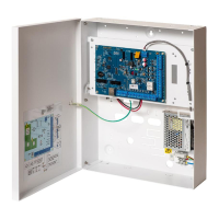
3 Power supply D/C Power Input:
The DC input power supply is applied to this 3-pin connection. PE is connected to
the earth lead from the mains supply which is wired to a connection point on the
metal housing.
4 Reset button
l
To reset the controller:
– Press this switch once.
l
To reset the programming settings to default and reboot the controller:
– Hold down the button until you are asked if a factory reset is desired.
– Select YES to reset to factory defaults.
Warning: Defaulting the controller to factory settings deletes all configuration files,
including backups, stored on the controller. All isolates and inhibits are also
deleted. It is recommended you backup your configuration to a PC before
defaulting the controller.
Note: This feature is not available if Engineer Lock is enabled.
5 Auxiliary 12V
output
The SPC controller provides an auxiliary 12V DC output that can be used to supply
power to expanders and devices such as latches, bells, etc. See Powering
expanders from the auxiliary power terminals on page265. The maximum
deliverable current is 750mA. Note: The amount of current drawn is subject to the
amount of time to be held up under battery conditions.
6 X-BUS
interface
This is the SPC communications bus used to network expanders together on the
system. See Wiring the X-BUS interface on page35.
7 Auxiliary 12V
output
Auxiliary 12V output An additional auxiliary 12V output provides power for outputs
(8 and 9). The maximum deliverable current for Auxillary 12V outputs (5 and 7) is
1500mA.
8 On-board
outputs
Output OP6 is a 12V open collector resistive output that shares a 400mA current
rating with the auxiliary 12V output. If the output is not connected to the 12V of the
controller and is powered from an external power source the 0V of the power
source needs to be connected to the controller 0V and the external power source
cannot exceed 12V.
9 ST- Output The ST- Output is a 12V open collector resistive output that shares a 400mA
current rating with the auxiliary 12V output.
10 Internal
bell/external
bell
Internal and external bell outputs (INT+, INT-, EXT+, EXT-) are resistive outputs
with a 400mA current rating. The BHO (Bell Hold Off), TR (Tamper Return), and
EXT outputs are used to connect an external bell to the controller. The INT+ and
INT- terminals are used to connect to internal devices such as an internal sounder.
See Wiring an internal sounder on page48.
11 Relay Outputs The SPCEvo controller provides two 3A, single pole, changeover relays that can
be used to drive external bell strobes or other devices..
12, 13 Detector 12V
outputs
The controller provides two 12V DC detector outputs that can be used to supply
power to detectors. The maximum deliverable current is 400mA.
SPC42/52/53/63 – Installation & Configuration Manual Controller hardware
© Vanderbilt 2023 32 I-200572
08.12.2023