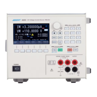
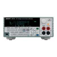
6253 DC Voltage Current Source/Monitor Operation Manual
5.6 Status Register Structure
5-21
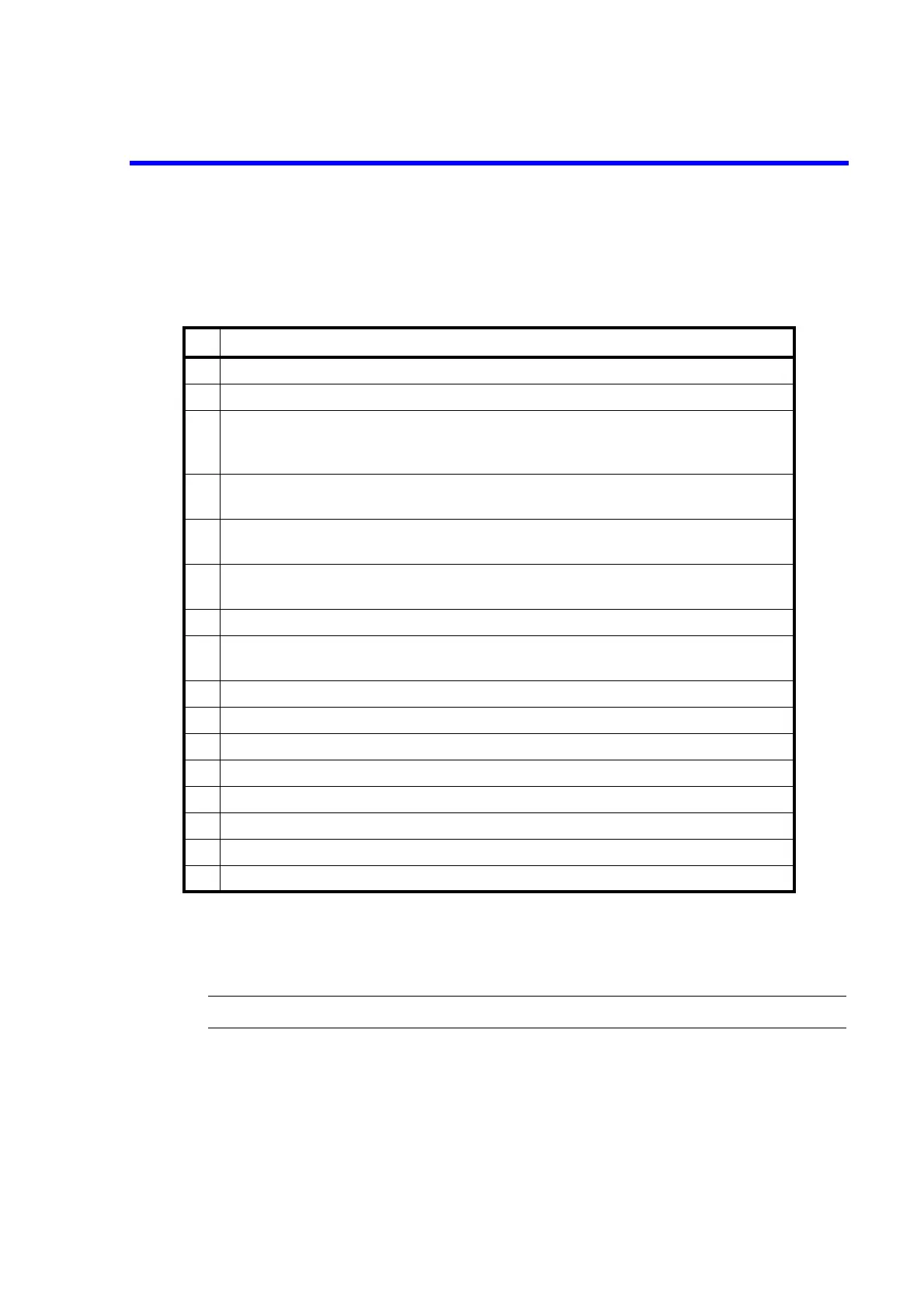
6. Error Register
The following table shows the allocations of the Error Register.
Common conditions in which the Error Register is cleared
• All cleared when the power is turned ON.
• All cleared by *CLS.
NOTE: The error register is not cleared when read by ERR?.
Table 5-8 Error Event Register (ERR)
bit Description
0 ON : Set to 1 when a self-test error occurs at power ON.
1 ON : Set to 1 when a self-test error occurs.
2 ON : Set to 1 when calibration data is lost in the self test at power ON, and the default
calibration values are used.
Set to 0 when the power is reset after recalibration.
3 ON : Set to 1 when an overload is detected.
Not set to 0 even if the overload is cleared.
4 ON : Set to 1 when “fan stopped” is detected.
Not set to 0 even if the “fan stopped” is cleared.
5 ON : Set to 1 when overheat is detected.
Not set to 0 even if the overheat is cleared.
6 ON : Set to 1 when the source unit malfunctions.
7 ON : Set to 1 when the saved parameters are lost in the self test at power ON and the
default parameters are used.
8 Always set to 0.
9 ON : Set to 1 when a calculation error occurs.
10 ON : Set to 1 when an over rang occurs.
11 Always set to 0.
12 ON : Set to 1 when a remote command argument error occurs.
13 ON : Set to 1 when a remote command execution error occurs.
14 ON : Set to 1 when a remote command format error occurs.
15 ON : Set to 1 when an unknown remote command is received.
 Loading...