COMMUNICATION AND VISUALIZATION TECHNOLOGIES
via Pastrengo, 7/C – 24068 Seriate (Bergamo)
[ENG]TC-430_Manual_1_116_0_A.doc
Copyright © 2016-2018 Aesys S.p.A.
All rights reserved
6. System status
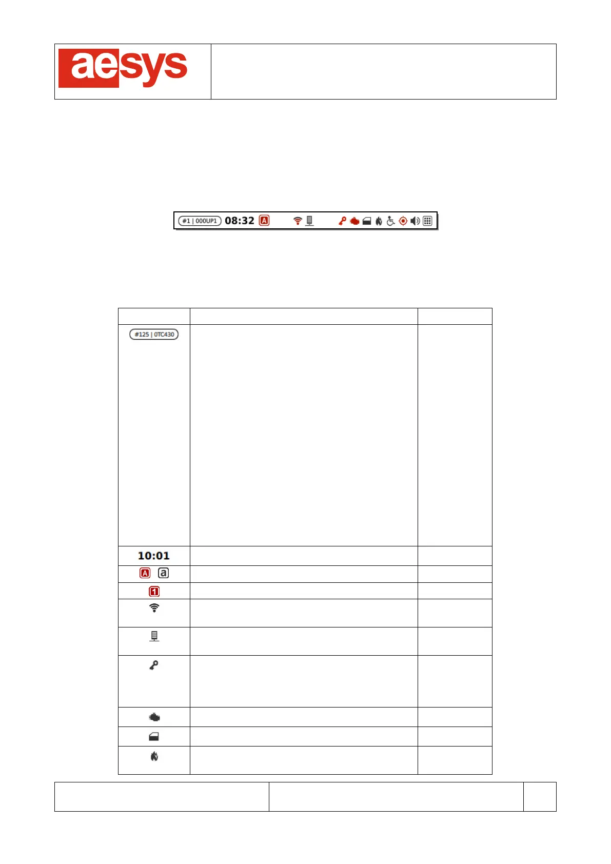
The current status of the system is reported by the status bar in the upper part of the screen (Figure 8).
Figure 8: Status bar
Table 2 describes all the parts composing the status bar.
The icon reports the current data level and the
current unit profile being used by TC-430™.
The current data level and the current unit
profile is available only if TC-430™ was loaded
with a VDB file; if a TRX file was loaded instead
only the label “TRX” is shown by the icon.
The icon is missing if no data files have been
loaded into the system.
If the icon is blinking then it means that there
are upcoming data updates to be processed
(data updates can be processed only while the
control unit is idling, meaning that no
destination, P/R, info, route number and dash
signs messages are selected nor any
navigation activity is on-going).
Please refer to [1] for further details about data
levels and unit profile.
Caps-lock enabled / disabled
Numeric mode keypad enabled
Wireless connection status (only shown when
the bus is under network coverage)
Server connection status (only shown when the
bus is connected to the station server)
Authorization key (red if an authorization key
has been detected; a small plus (“+”) appears
next to the icon if the key has been used for
recognizing a driver)
Engine status (grayed out if the engine is off)
Doors status (flashing red if doors are open)
Emergency button status (flashing red if
emergency mode is active)