11.4 Emergency handling
An emergency button (or pedal) can be connected to the TC-430™ in order to properly handle emergency
events on-board (such as robbery or other criminal events). Please refer to TC-430™ installation and cabling
documentation for further details about button/pedal connection and refer to paragraph 9.6 for button/pedal
status configuration).
TC-430™ enters the emergency mode after a 3-second long press of the button/pedal. The emergency
mode is notified by a flashing red emergency icon in the status bar (see paragraph 6. ).
When TC-430™ enters the emergency mode the control unit searches for a destination coded “ZZZZZZ”
within the current data file being used by the system and silently publish it on external bus LED signs (such a
destination should implement a message like “CALL 911” or similar); no P/R messages are shown by LED
signs during the emergency mode.
If a destination coded “ZZZZZZ” cannot be found within the current data file, then the string “CALL 911” is
published on external signs using the default font and publication template provided by signs themselves
(actual visualization may vary depending on specific LED signs firmware implementations).
Emergency mode can be left long pressing the emergency button/pedal for 10 seconds. When TC-430™
leaves the emergency mode, the emergency icon in the status bar is turned off (paragraph 6. ) and normal
LED signs publication is restored.
11.5 Data file storage
It is possible to download the current data file from TC-430™ to a USB mass storage device (e.g. for copying
the same exact destinations/messages database to another control unit).
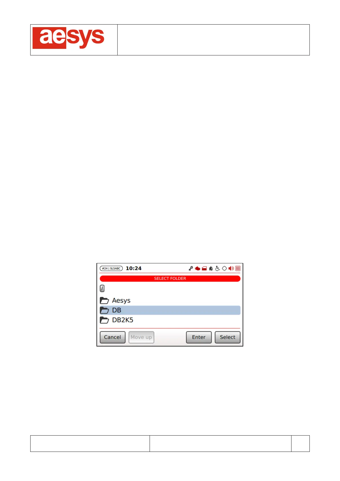
Current data file is downloaded by selecting “Menu
Store data file”. Screen in Figure 134 is shown for
allowing the user to select the folder on the USB mass storage to download the current data file to.
Figure 134: Current data file storage folder selection
“Enter”, “Select”, “Move up” respectively enters, selects and leaves (upward) the current folder. After folder
selection the screen in Figure 135 is shown for letting the user decide the name to be assigned to the file to
be saved on USB mass storage.