COMMUNICATION AND VISUALIZATION TECHNOLOGIES
via Pastrengo, 7/C – 24068 Seriate (Bergamo)
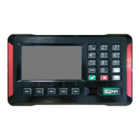
Figure 52: Mass storage usage
8.2 Hardware monitor
Hardware monitor is accessible by selecting “Menu
Diagnostics menu
Hardware monitor”. The screen
in Figure 53 is shown.
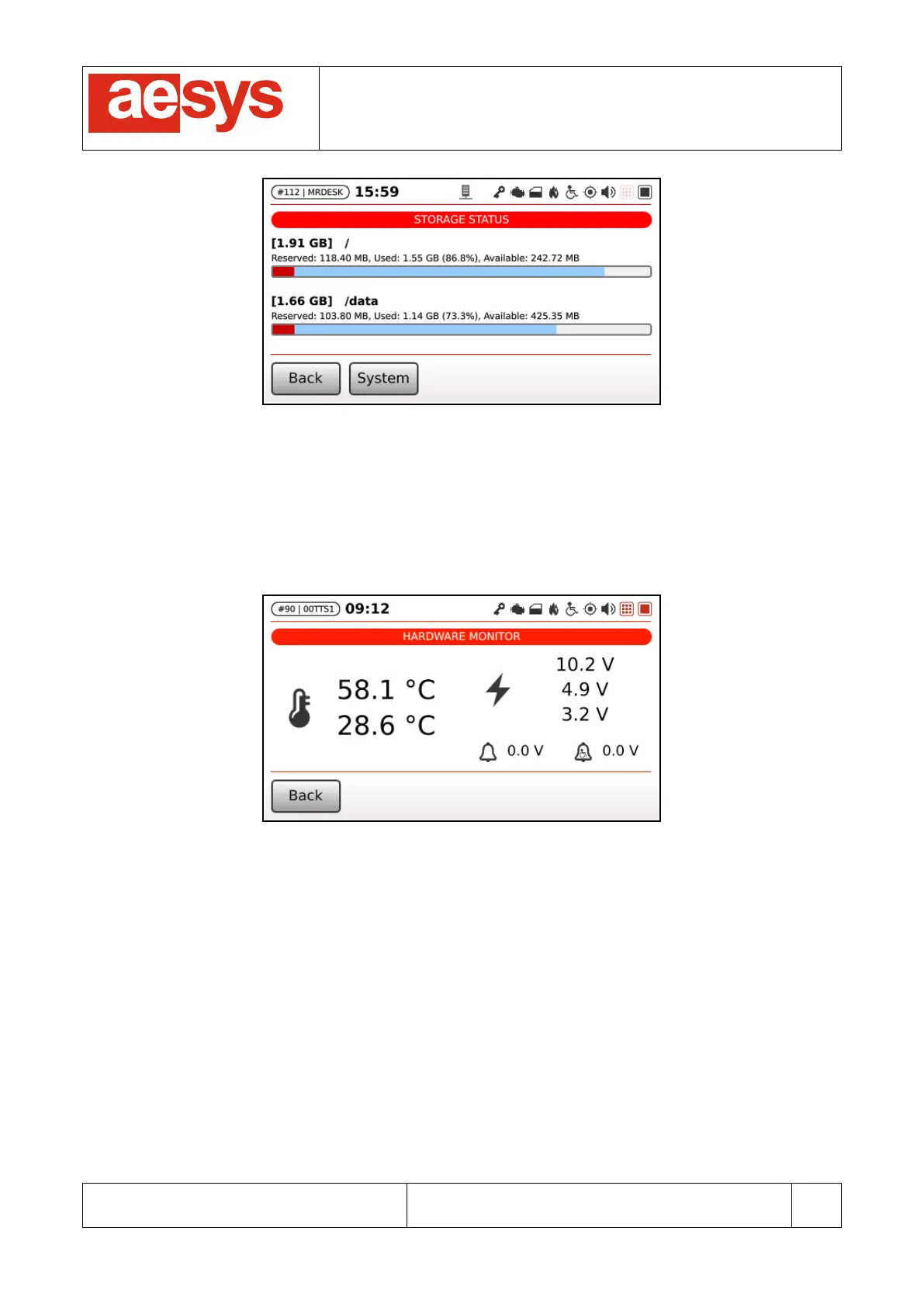
Figure 53: Hardware monitor
Hardware monitor shows:
- temperature sensors on the left (CPU temperature and case temperature respectively);
- power supply status on the right (respectively main power input, 5V and 3.3V);
- stop request analog signals voltage on bottom-right corner.
Temperatures and power supply values get properly colorized in order to notify warning (orange) or critical
(red) conditions.
Stop request icons (standard and wheelchair request) turn red when the voltage is above 4.5V threshold (+/-
0.5V hysteresis). The threshold has been studied in order to conform to the majority of bus installations, but
can anyway be configured to different values. Please contact Aesys® customer service if in need to change
threshold and/or hysteresis figures.