Preparing for Operation
Using the injector fan
35
Caution This procedure requires protection against electrostatic discharge. Use a static
control wrist strap connected to a ground (part no. 9300-0969 for large wrists
or part no. 9300-0970 for small wrists). If you do not use static protection, you
may damage the electronics of the injector. Do not touch any of the electrical
components, especially the microprocessor.
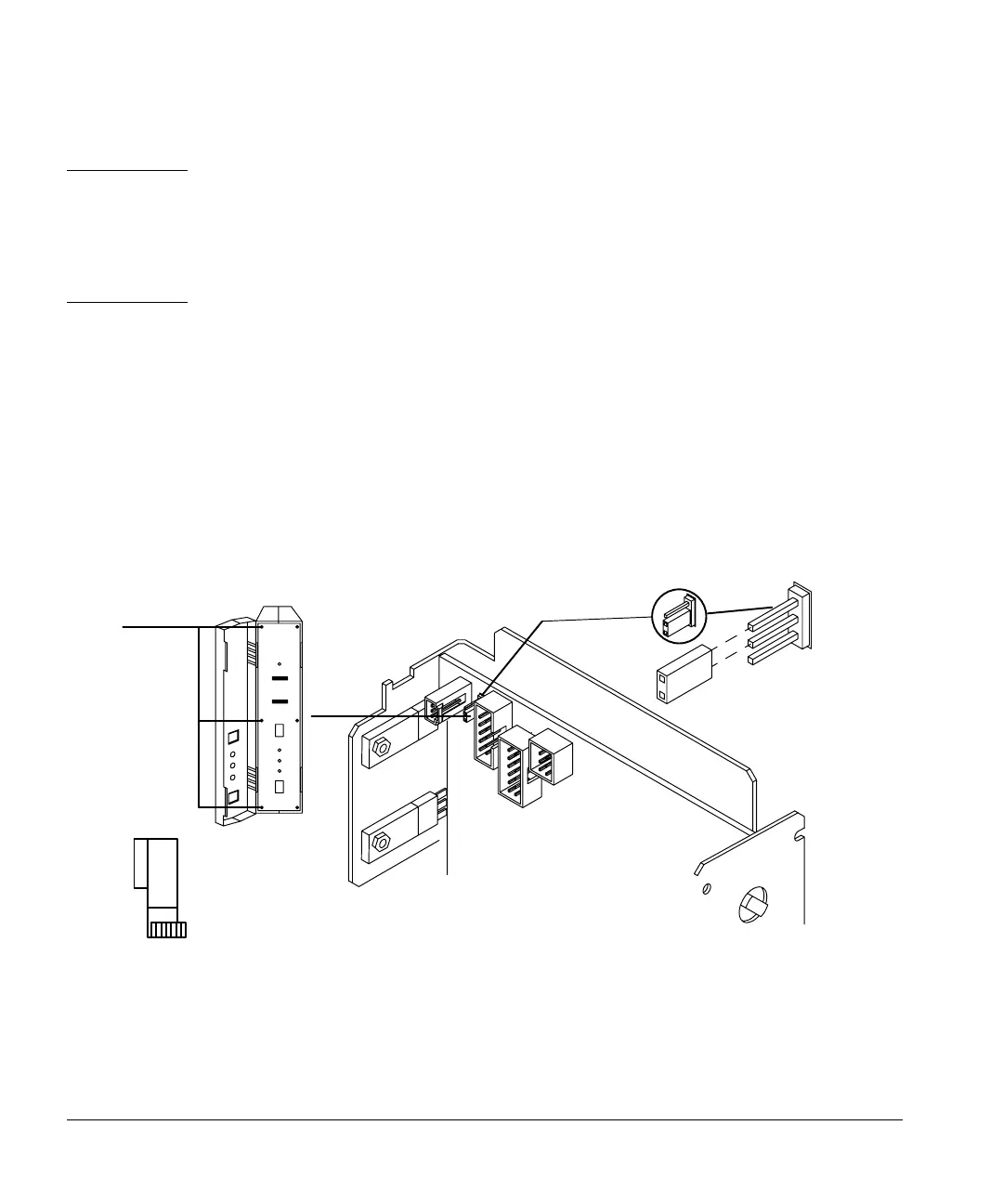
3. Open the door to the injector electronics assembly, and remove the three
screws on the left edge of the panel with a No. 1 Point Pozidrive
screwdriver.
4. Open the left-hand side of the assembly. Remove the blue ribbon cable
(P3) so P6 is more visible. Locate the P6 jumper switch on the top left
front corner of the printed circuit board.
5. Connect the P6 jumper so that it covers the top two prongs on the circuit
board labeled OFF. See Figure 26. Return the ribbon cable to its original
position.
Figure 26. P6 jumper setting
6. Close the left-hand side of the assembly, and replace the three screws on
the left edge of the front panel.
Screws
ON
P6
OFF