5. Set up the trigger:
Press [
Trigger
], [
trigger type
], [
internal source
], [
return
], [
ch1 delay
], 3, [
ms
].
This example uses the 32 DVB QAM signal from the Signals Disk. This
signal was generated following a procedure similar to that shown in
chapter 9, ‘’To create an ideal digitally modulated signal.’’ The method
used to create this signal results in some invalid data at the beginning of
the time record. The 3 milli-second trigger delay removes the invalid data
from the measurement.
When you supply any signal to the channel 1 input you need to select
appropriate center frequency, span, range, and triggering parameters prior
to demodulating the signal. Display formats and measurement types may
be applied and changed after demodulation.
This task sets [
max time pts] to its maximum value (4096), which allocates the
maximum amount of measurement memory for digital video demodulation.
This lets you choose larger result lengths, search lengths, and
points-per-symbol. For additional details about allocating memory for
digital video demodulation, see ‘’Parameter Interactions’’ in the Video
Demodulation Concepts chapter and see online help for [
max time points],
(press [
Help], then press [max time points]).
QAM and DVB QAM measurements treat I/Q origin offset differently. QAM
measurements remove I/Q origin offset, DVB QAM measurements do not
remove I/Q origin offset. Both demodulation formats report I/Q origin
offset (in the symbol table).
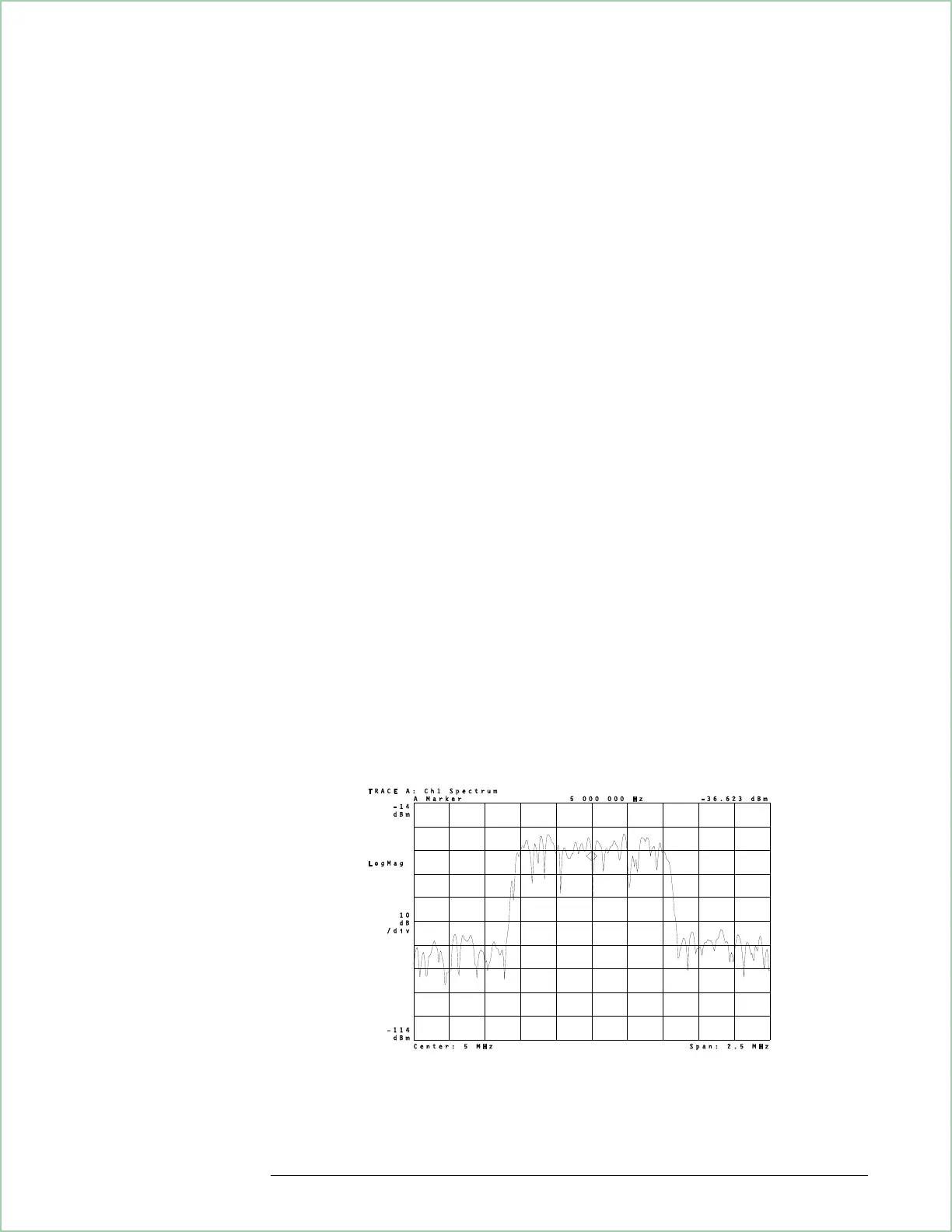
The spectrum of a 32 DVB QAM signal before demodulation.
Using Video Demodulation
(Opt. AYH)
9 - 9
 Loading...


