104 6000 Series Oscilloscope User’s Guide
2 Front-Panel Controls
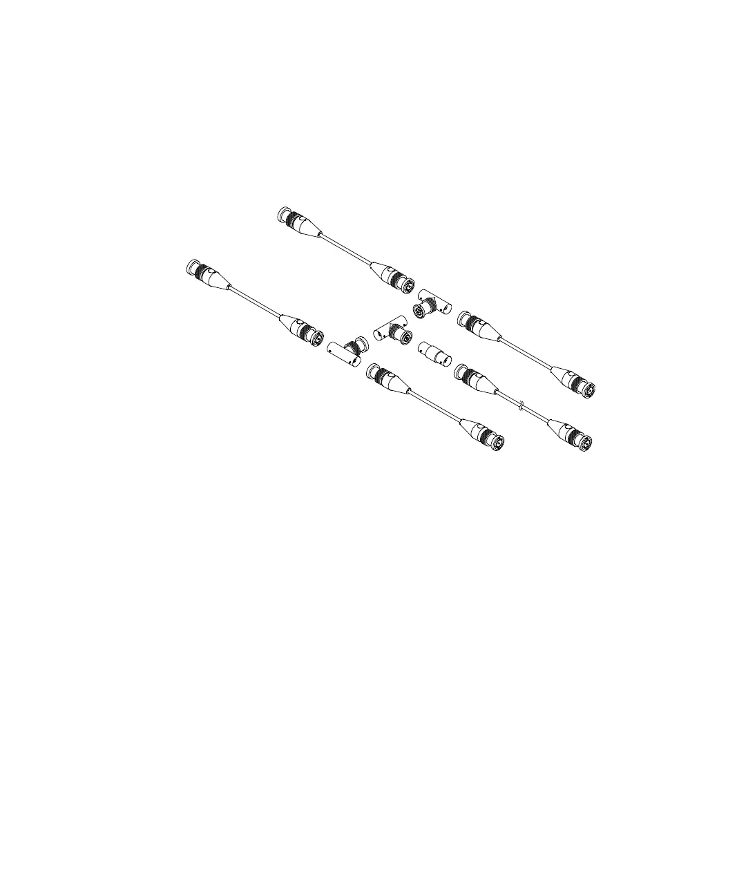
For a 4-channel oscilloscope, connect BNC tees to the
equal-length cables as shown below. Then connect a
BNC(f)-to-BNC(f) (barrel connector) to the tee as shown
below.
Figure 11 User Calibration cable for 4-channel oscilloscope
1 Connect a BNC cable (40 inches maximum) from the TRIG
OUT connector on the rear panel to the BNC barrel
connector.
2 Press the Utility key, then press the Service softkey.
3 Begin the Self Cal by pressing the Start User Cal softkey.
4 When the User Cal is completed, set the rear-panel
CALIBRATION switch to PROTECTED.
User Cal Status
Pressing Utility&Service&User Cal Status displays the summary
results of the previous User Cal, and the status of probe
calibrations for probes that can be calibrated. Note that passive
Longer cable
to TRIG OUT
To Channel 3
To Channel 1
To Channel 4
To Channel 2
 Loading...