66 6000 Series Oscilloscope User’s Guide
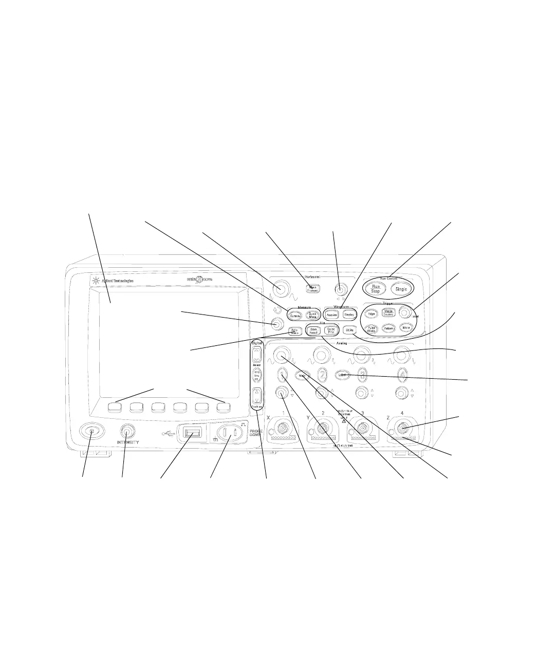
2 Front-Panel Controls
4-Channel 6000A Series Oscilloscope Front Panel
The following diagram shows the front panel of the 6000A
Series 4-channel oscilloscopes. The controls of the 2-channel
oscilloscopes are very similar. For a diagram showing the
differences of the 2-channel oscilloscope, see page 72.
Figure 6 6000A Series 4-Channel Oscilloscope Front Panel
4
Probe
Compensation
Terminals
22
Display
20
Horizontal
Sweep Speed
Control
6
Vertical
Position
Control
25
Softkeys
17
Waveform
Keys
21
Measure
Keys
12
Label Key
23
Entry
Knob
24
AutoScale
Key
18
Horizontal
Delay
Control
1
Power
switch
2
Intensity
Control
3
USB
Port
13
File Keys
15
Trigger
Controls
16
Run
Controls
7
Channel
On/Off
Key
8
Math
Key
11
Channel
Input BNC
10
AutoProbe
Interface
5
Digital
Channel
Controls
19
Horizontal
Main/Delayed
Key
9
Vertical
Sensitivity
Control
14
Utility
Key
 Loading...