Home
Agilent Technologies
Test Equipment
MSO6012A
Agilent Technologies MSO6012A User Manual
4
of 1
of 1 rating
371 pages
Give review
Manual
Specs
To Next Page
To Next Page
To Previous Page
To Previous Page
Loading...
Viewing and Measuring Digital Signals
3
6000 Series Oscilloscope User’s Guide
115
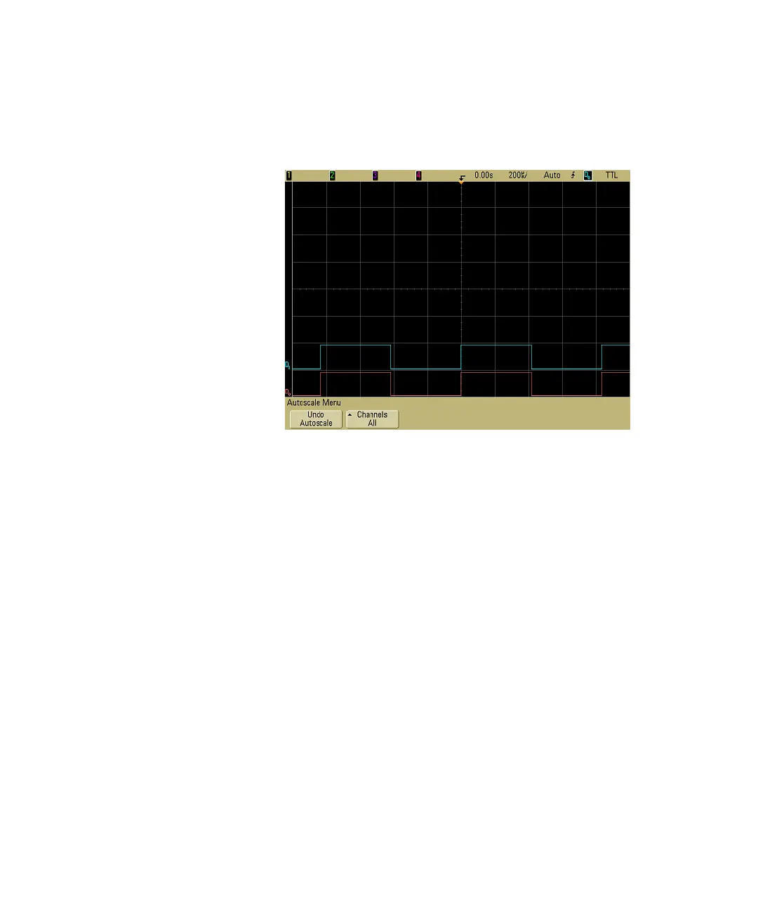
configuration by pressing the
Save/
Recall
ke
y
, then
the
Default
Setup
sof
tke
y. Then pr
ess the
AutoScale
ke
y. Y
ou s
hould see a
display similar to the follo
wing.
Figure 12
AutoScale of di
gital channe
ls 0 & 1 (MSO models only
)
115
117
Table of Contents
Default Chapter
3
Safety Notices
3
Table of Contents
10
Getting Started
20
To Inspect Package Contents
22
To Adjust the 6000A Series Handle
27
To Mount the Oscilloscope in a Rack
28
To Mount the 6000A Series Oscilloscope in a Rack
28
To Mount the 6000L Series Oscilloscope in a Rack
28
Ventilation Requirements
31
To Power-On the Oscilloscope
32
AC-Powered 6000 Series
32
Battery-Powered 6000A Series
32
The Remote Interface
37
To Establish a LAN Connection (6000A Series)
38
To Establish a LAN Connection (6000L Series)
39
To Establish a Point-To-Point LAN Connection
41
To Use the Web Interface
42
Controlling the Oscilloscope Using a Web Browser
43
Setting a Password
45
Scrolling and Monitor Resolution
48
Identify Function
48
To Connect the Oscilloscope Probes
50
To Verify Basic Oscilloscope Operation
51
To Compensate the Oscilloscope Probes
53
To Calibrate the Probes
54
Passive Probes Supported
54
Active Probes Supported
55
By 300 Mhz, 500 Mhz, and 1 Ghz Bandwidth Models
55
By 100 Mhz Bandwidth Models
56
Using Quick Help
57
Quick Help Languages
58
Front-Panel Controls
60
6000L Series Oscilloscope Controls
61
Front and Rear Panel Controls and Connectors
62
6000A Series Oscilloscope Front-Panel Controls
65
Conventions
66
Graphic Symbols in Softkey Menus
66
4-Channel 6000A Series Oscilloscope Front Panel
67
Front Panel Controls
68
2-Channel 6000A Series Oscilloscope Front Panel (Differences Only)
73
Interpreting the Display
74
6000A Series Front-Panel Operation
75
To Adjust the Waveform Intensity
75
To Adjust the Display Grid (Graticule) Intensity
75
To Start and Stop an Acquisition
76
To Make a Single Acquisition
77
To Pan and Zoom
78
Choosing Auto Trigger Mode or Normal Trigger Mode
79
Using Autoscale
79
To Set the Probe Attenuation Factor
80
Using the Analog Channels
82
To Set up the Horizontal Time Base
87
To Make Cursor Measurements
94
To Make Automatic Measurements
95
Using Labels
96
To Print the Display
100
To Set the Clock
100
To Set up the Screen Saver
101
To Set the Waveform Expansion Reference Point
102
To Perform Service Functions
103
User Calibration
103
Self Test
106
About Oscilloscope
106
To Restore the Oscilloscope to Its Default Configuration
107
Viewing and Measuring Digital Signals
110
To Connect the Digital Probes to the Circuit under Test
111
Acquiring Waveforms Using the Digital Channels
114
To Display Digital Channels Using Autoscale
115
Example
115
Interpreting the Digital Waveform Display
117
To Switch All Digital Channels on or off
118
To Switch Groups of Channels on or off
118
To Switch a Single Channel on or off
118
To Change the Displayed Size of the Digital Channels
119
To Reposition a Digital Channel
119
To Change the Logic Threshold for Digital Channels
120
To Display Digital Channels as a Bus
121
Triggering the Oscilloscope
126
Selecting Trigger Modes and Conditions
129
To Select the Mode and Coupling Menu
129
Trigger Modes: Normal and Auto
130
To Select Trigger Coupling
132
To Select Trigger Noise Rejection and HF Rejection
132
To Set Holdoff
133
The External Trigger Input
135
2-Channel Oscilloscope External Trigger Input
135
4-Channel Oscilloscope External Trigger Input
137
Trigger Types
138
To Use Edge Triggering
139
Trigger Level Adjustment
140
To Use Pulse Width Triggering
141
Qualifier Time Set Softkey
143
To Use Pattern Triggering
144
To Use CAN Triggering
146
To Use Duration Triggering
150
Qualifier Time Set Softkey
152
To Use Flexray Triggering
153
Modes of BUSDOCTOR Control/Operation
153
Setting up the Oscilloscope and BUSDOCTOR 2
154
Triggering on Flexray Frames, Times, or Errors
158
To Use I2C Triggering
162
To Use Nth Edge Burst Triggering
168
To Use LIN Triggering
170
To Use Sequence Triggering
173
Define the Find: Stage
175
Define the Trigger On: Stage
176
Define the Optional Reset On: Stage
178
Adjust the Trigger Level
179
To Use SPI Triggering
180
Assign Source Channels to the Clock, Data, and Frame Signals
182
Set up the Number of Bits in the Serial Data String and Set Values for those Data Bits
185
Resetting All Bits in the Serial Data String to One Value
185
To Use TV Triggering
185
Example Exercises
189
To Trigger on a Specific Line of Video
189
To Trigger on All Sync Pulses
191
To Trigger on a Specific Field of the Video Signal
192
To Trigger on All Fields of the Video Signal
193
To Trigger on Odd or Even Fields
194
To Use USB Triggering
197
The Trigger out Connector
199
Triggers
199
Source Frequency
199
Source Frequency/8
199
Making Measurements
200
To Use the XY Horizontal Mode
201
Math Functions
206
Math Scale and Offset
207
Multiply
208
Subtract
210
Differentiate
212
Integrate
214
FFT Measurement
217
FFT Operation
219
Square Root
224
Cursor Measurements
226
To Make Cursor Measurements
226
Cursor Examples
230
Automatic Measurements
233
To Make an Automatic Measurement
234
To Set Measurement Thresholds
235
Time Measurements
237
Delay and Phase Measurements
241
Voltage Measurements
244
Overshoot and Preshoot Measurements
249
Displaying Data
252
Pan and Zoom
253
To Pan and Zoom a Waveform
254
To Set the Waveform Expansion Reference Point
254
Antialiasing
255
Using the XGA Video Output
255
Display Settings
256
Infinite Persistence
256
Grid Intensity
257
Vectors (Connect the Dots)
257
Varying the Intensity to View Signal Detail
258
Acquisition Modes
260
At Slower Sweep Speeds
260
Selecting the Acquisition Mode
260
Normal Mode
261
Peak Detect Mode
261
High Resolution Mode
261
Averaging Mode
262
Realtime Sampling Option
264
Using Serial Decode
266
To Decode I 2 C Data
267
To Decode SPI Data
271
To Decode CAN Data
276
CAN Totalizer
281
To Decode LIN Data
283
To Decode Flexray Data
289
Flexray Totalizer
293
To Reduce the Random Noise on a Signal
295
HF Reject
295
LF Reject
296
Noise Rejection
296
To Capture Glitches or Narrow Pulses with Peak Detect and Infinite Persistence
297
Using Peak Detect Mode to Find a Glitch
298
How Autoscale Works
300
Undo Autoscale
300
Specifying the Channels Displayed after Autoscale
301
Preserving the Acquisition Mode During Autoscale
301
Saving and Printing Data
302
To Configure Printing
303
Selecting a Print File Format
303
Selecting Print Options
306
Print Palette
306
To Print the Display to a File
307
To Print the Display to a USB Printer
308
Supported Printers
309
Printers
309
Secure Environment Mode Option
311
Saving and Recalling Traces and Setups
313
To Autosave Traces and Setups
314
To Save Traces and Setups to Internal Memory or to Overwrite an Existing USB Mass Storage Device File
315
Device
316
To Save Traces and Setups to a New File on the USB Mass Storage Device
316
To Recall Traces and Setups
318
To Use the File Explorer
319
Reference
322
Upgrading to an MSO or Adding Memory Depth
323
Software and Firmware Updates
323
To Set up the I/O Port
324
Using the 10 Mhz Reference Clock
325
Sample Clock and Frequency Counter Accuracy
325
Supplying an External Timebase Reference
325
To Supply a Sample Clock to the Oscilloscope
325
To Synchronize the Timebase of Two or more Instruments
327
To Check Warranty and Extended Services Status
327
To Return the Instrument
328
To Clean the Oscilloscope
328
Digital Channel Signal Fidelity: Probe Impedance and Grounding
329
Input Impedance
329
Probe Grounding
331
Best Probing Practices
333
To Replace Digital Probe Leads
334
Binary Data (.Bin)
335
Binary Data in MATLAB
335
Binary Header Format
335
Example Program for Reading Binary Data
339
Examples of Binary Files
340
Characteristics and Specifications
342
6000A Series and 6000L Series Environmental Conditions
343
Overvoltage Category
343
Pollution Degree
343
Pollution Degree Definitions
343
6000A Series and 6000L Series Measurement Category
344
Measurement Category
344
Measurement Category Definitions
344
6000A Series and 6000L Series Transient Withstand Capability
345
6000A Series Oscilloscope Specifications
346
6000A Series Oscilloscope Characteristics
347
6000L Series Specifications and Characteristics
357
Performance Characteristics
357
Trigger System
359
Measurement Features
360
General Characteristics
361
Power Requirements
362
Environmental Characteristics
362
Ordering Information
363
Index
364
4
Based on 1 rating
Ask a question
Give review
Questions and Answers:
Need help?
Do you have a question about the Agilent Technologies MSO6012A and is the answer not in the manual?
Ask a question
Agilent Technologies MSO6012A Specifications
General
Brand
Agilent Technologies
Model
MSO6012A
Category
Test Equipment
Language
English
Related product manuals
Agilent Technologies MSO8104A
14 pages
InfiniiVision 3000 MSO-X 3012A
424 pages
Medalist i3070 5i Series
181 pages
Agilent Technologies 3070
116 pages
Agilent Technologies U1602B
227 pages
Agilent Technologies 86100C
92 pages
Agilent Technologies E7495A RF
15 pages
Agilent Technologies HP 83712B
251 pages
Agilent Technologies 5000 Series
126 pages
93000 SOC Series
632 pages
E4406A VSA Series
420 pages
InfiniiVision 5000 Series
428 pages
 Loading...