234 Agilent X-Series Signal Generators User’s Guide
Basic Digital Operation (Option 653/655/656/657)
Understanding Option 012 (LO In/Out for Phase Coherency) with Multiple Baseband Generator Synchronization
2x2 MIMO (LO In/Out for Phase Coherency) Configuration
For the 2x2 MIMO (LO In/Out for phase coherency) setup, the LO from the master MXG/EXG can be
run through a power splitter and used as the LO input to both the master and the slave signal
generators. No external source is required.
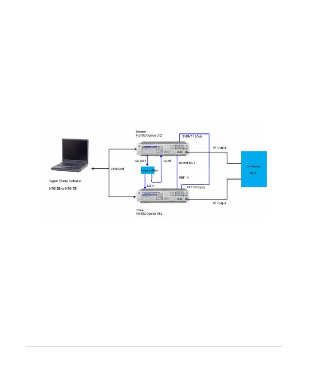
To generate phase coherent signals for a 2x2 MIMO configuration, the master MXG LO OUT is
connected via a power splitter to the slave LO IN. The LO OUT provides a sufficient amplitude LO
signal when connected directly, to drive the Slave MXG/EXG(s), thus providing phase coherency for
the RF output signals. In this example, we show two MXG signal generators with Option 012
connected for a phase coherent 2x2 MIMO solution. Refer to Figure 8- 30.
Figure 8-30 2x2 MIMO (LO In/Out for Phase Coherency) Equipment Setup
3x3 and 4x4 MIMO (LO In/Out for Phase Coherency) Configurations
For a 3x3 and 4x4 MIMO (LO In/Out for phase coherency) setups, an additional analog source is
needed to provide the higher LO power required by the power splitter and the additional
instruments.
Splitting the LO output four ways causes too much loss to drive the LO input of the N5172B/82Bs in
the system. Also, there is no amplitude adjustment to the LO output of the N5172B/82B. To generate
phase coherent signals for 3x3 and 4x4 configurations with the MXG/EXG, an external Master LO is
needed to provide a sufficient amplitude LO input signal to the vector MXG/EXGs (refer to Figure
8- 31 on page 235).
NOTE The Master LO is not controlled by any of the Signal Studio software, but must be set
manually—via the RF frequency settings on the master signal generator—by the user to the
desired frequency and amplitude.
Note:
To optimize the phase coherence, the same length SMA flexible cable is recommended for the output of the 2–way splitter
connections to the LO IN of the signal generator with Option 012 (see page 232).
To minimize synchronization delay, the Agilent BNC cable 10502A is the recommended cable for the rear panel daisy chain
connections on the EVENT 1 and PAT TRIG BNC connectors (see page 232).

 Loading...

