254 Agilent X-Series Signal Generators User’s Guide
Digital Signal Interface Module (Option 003/004)
Clock Timing
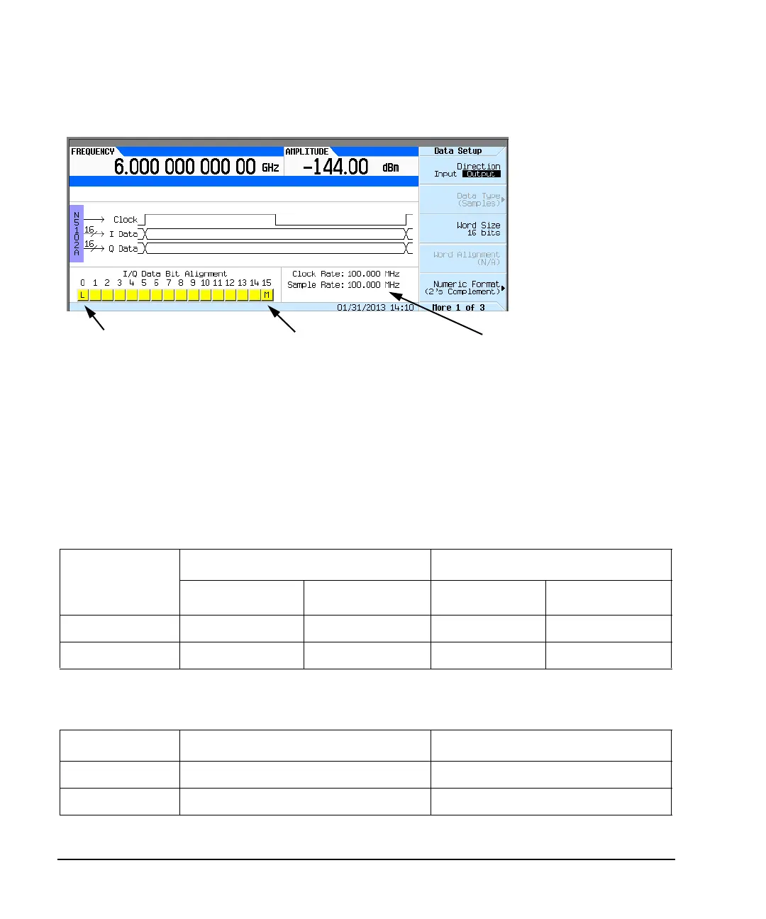
Figure 10-1 Data Setup Menu for a Parallel Port Configuration
The N5102A module clock rate is set using the Clock Rate softkey and has a range of 1 kHz to
400 MHz. The sample rate is automatically calculated and has a range of 1 kHz to 200 MHz. These
ranges can be smaller depending on logic type, data parameters, and clock configuration.
Maximum Clock Rates
The N5102A module maximum clock rate is dependent on the logic and signal type. Table 10- 1 and
Table 10- 2 show the warranted rates and the maximum clock rates for the various logic and signal
types. Notice that LVDS in the output mode using an IF signal is the only logic type where the
warranted and maximum rates are the same.
Ta bl e 10-1 Warranted Parallel Output Level Clock Rates and Maximum Clock Rates
Logic Type
Warranted Level Clock Rates Maximum Clock Rates (typical)
IQ Signal Type
IF Signal Type
1
1
The IF signal type is not available for a serial port configuration.
IQ Signal Type IF Signal Type
LVTTL and CMOS 100 MHz 100 MHz 150 MHz 150 MHz
LVDS 200 MHz 400 MHz 400 MHz 400 MHz
Ta bl e 10-2 Warranted Parallel Input Level Clock Rates and Maximum Clock Rates
Logic Type Warranted Level Clock Rates Maximum Clock Rates (typical)
LVTTL and CMOS 100 MHz 150 MHz
LVDS 200 MHz 200 MHz
Clock and sample rates
Least significant bit
Most significant bit

 Loading...

