EasyManuals Logo

Allen-Bradley ControlLogix User Manual

Allen-Bradley ControlLogix
203 pages
To Next Page IconTo Next Page
To Previous Page IconTo Previous Page
Page #125 background imageLoading...
Page #125 background image
1756-6.5.3 - December 1999
PLC-5C to Logix5550 Controller: Scheduled Communications 8-23
Verify the Message
1. Restore RSLogix5550.
2. Double-click on the Controller Tags folder in the Project window and
select the Monitor Tags tab.
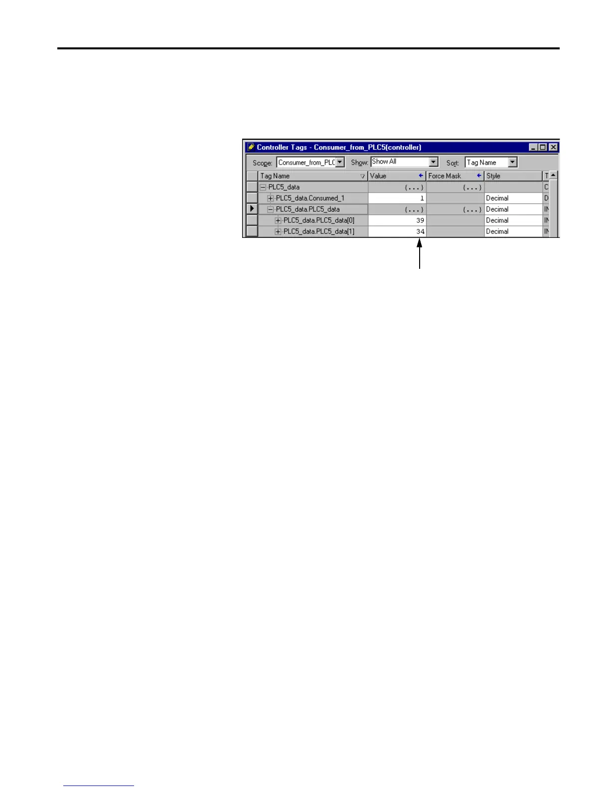
3. Expand the PLC5_data tag.
In the PLC5_data.PLC5_data array you should see the data sent from
N10:0 and N10:1 incrementing once a second with an offset of 5.
This completes the PLC-5C to Logix5550 scheduled communications
example.
You should see these values
changing with an offset of 5.

Table of Contents

Other manuals for Allen-Bradley ControlLogix

Questions and Answers:

Question and Answer IconNeed help?

Do you have a question about the Allen-Bradley ControlLogix and is the answer not in the manual?

Allen-Bradley ControlLogix Specifications

General IconGeneral
CommunicationEtherNet/IP, ControlNet, DeviceNet, DH+
I/O CapacityUp to 128, 000 I/O points (varies by configuration)
RedundancySupported (with specific modules)
Programming SoftwareRockwell Automation Studio 5000 Logix Designer
Operating Temperature0°C to 60°C (32°F to 140°F)
Programming LanguagesLadder Logic, Function Block Diagram, Structured Text, Sequential Function Chart
ModularityYes
CertificationsUL, CE
Processor TypeMultiple options available, including standard, safety, and extreme environment processors
Power SupplyMultiple options available, including standard and redundant power supplies with various voltage ranges (e.g., 24V DC, 120/240V AC)

Related product manuals