1756-6.5.3 - December 1999
Chapter
9
PLC-5C to PLC-5C Unscheduled Messaging
Over Two ControlNet Networks
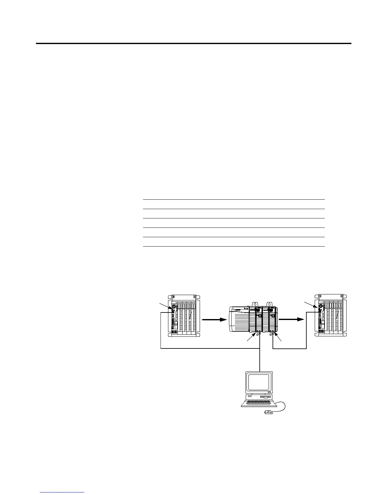
About the Example Application
In this example you establish communications between two PLC-5C
processors on different ControlNet networks. Two 1756-CNB modules in
the same ControlLogix chassis are used to bridge the networks. The
1756-CNB modules are in slots 1 and 3 and are configured as nodes 1 and 6,
respectively. The application sends an unscheduled PLC-5C Typed Write
message from the PLC-5C processor on ControlNet network #1 (node 11)
to the PLC-5C processor on ControlNet network #2 (node 16).
Set Up the Example
Application
Change your system configuration to that shown below:
• Verify that the node addresses for the 1756-CNB modules are 1 and 6 as
shown.
• Verify that the ControlNet node addresses for the PLC-5C processors are
11 and 16 as shown.
What you will do See page
Set Up the Example Application 9-1
Create the Example Application 9-2
Create the Ladder Program 9-3
Download the Program 9-5
Test the Example Application 9-6
ControlNet Network #1
1756-CNB
(Node 1)
PLC-5C
ControlLogix Chassis
PC with
1784-KTCX15
Interface
Message
Slot 1 3
(Node 11)
1756-CNB
(Node 6)
PLC-5C
(Node 16)
Message
ControlNet Network #2
1771 I/O Chassis
1771 I/O Chassis

 Loading...


