EasyManuals Logo

Allen-Bradley ControlLogix User Manual

Allen-Bradley ControlLogix
203 pages
To Next Page IconTo Next Page
To Previous Page IconTo Previous Page
Page #121 background imageLoading...
Page #121 background image
1756-6.5.3 - December 1999
PLC-5C to Logix5550 Controller: Scheduled Communications 8-19
Create the PLC-5C Program
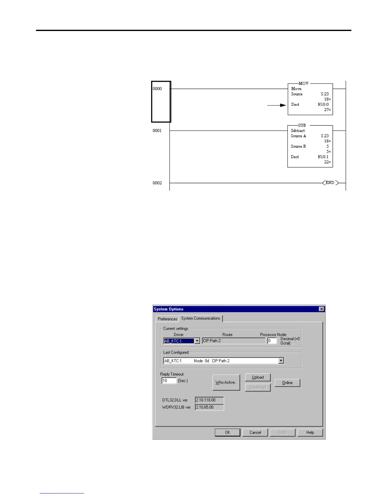
1. Enter the following ladder program:
2. From the Edit menu, select Verify Project.
3. Save the file.
Download the PLC-5C Program
1. From the Comms menu, select System Communications.
The System Options window will appear with the System
Communications tab open.
2. Select AB_KTC-1 as the Driver and click on Who Active.
N10 is the Output File configured
in RSNetWorX for ControlNet.
The data will be sent to an integer
array of size 2 (PLC5_data) in the
Logix5550 processor.

Table of Contents

Other manuals for Allen-Bradley ControlLogix

Questions and Answers:

Question and Answer IconNeed help?

Do you have a question about the Allen-Bradley ControlLogix and is the answer not in the manual?

Allen-Bradley ControlLogix Specifications

General IconGeneral
CommunicationEtherNet/IP, ControlNet, DeviceNet, DH+
I/O CapacityUp to 128, 000 I/O points (varies by configuration)
RedundancySupported (with specific modules)
Programming SoftwareRockwell Automation Studio 5000 Logix Designer
Operating Temperature0°C to 60°C (32°F to 140°F)
Programming LanguagesLadder Logic, Function Block Diagram, Structured Text, Sequential Function Chart
ModularityYes
CertificationsUL, CE
Processor TypeMultiple options available, including standard, safety, and extreme environment processors
Power SupplyMultiple options available, including standard and redundant power supplies with various voltage ranges (e.g., 24V DC, 120/240V AC)

Related product manuals