1756-6.5.3 - December 1999
Installing the ControlNet Network 2-9
Installing the PLC-5C
Controllers
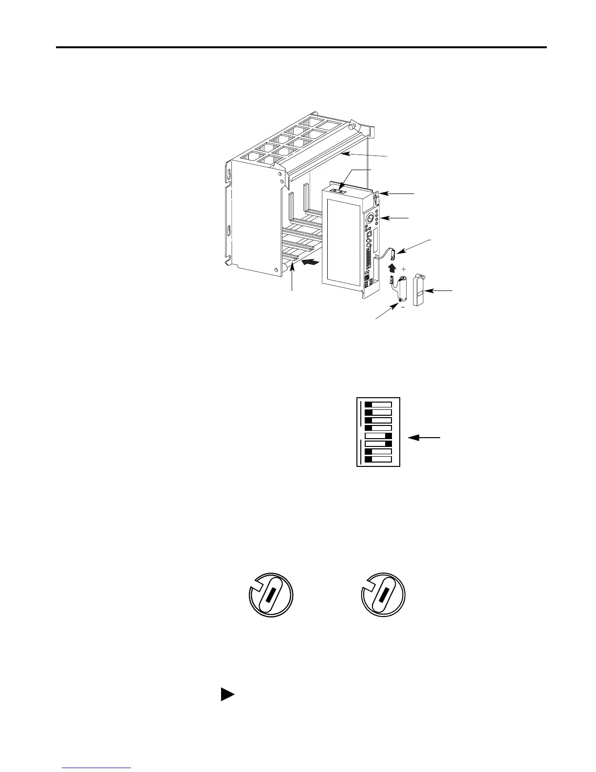
Install the PLC-5C controller in a 1771 I/O chassis.
1. Set the backplane switches in the I/O chassis so that you can download
the ladder logic programs in the example applications. Put switches 5
and 6 in the “on” position, and all of the others in the “off” position.
2. Set the PLC-5C ControlNet node addresses using the two 10-digit rotary
switches on top of the PLC-5C modules.
For the example applications use node addresses 11 and 16.
3. Insert the PLC-5C into the 1771 chassis.
4. Connect the PLC-5C’s ControlNet port to the ControlNet network.
See the ControlNet 1.5 PLC-5 Programmable Controller User
Manual, publication 1785-6.5.22, for further information.
Card Guides
Battery
Battery
Battery
PLC-5/40C Controller
Lift Ejector Tab
Locking Bar
Connector
Cover
ControlNet Node Address Switches
PLC-5C Controller and 1771 I/O Chassis
1
2
3
4
56
7
8
OPEN
Switches 5 and 6 “on”
ControlNet PLC-5C controller’s NET address = 11
30
40
50
60
70
80
90
00
10
20
3
4
5
6
7
8
9
0
1
2
30
40
50
60
70
80
90
00
10
20

 Loading...


