EasyManuals Logo

Allen-Bradley ControlLogix User Manual

Allen-Bradley ControlLogix
203 pages
To Next Page IconTo Next Page
To Previous Page IconTo Previous Page
Page #38 background imageLoading...
Page #38 background image
1756-6.5.3 - December 1999
3-4 Logix5550 to Logix5550 Controller: Unscheduled Messaging
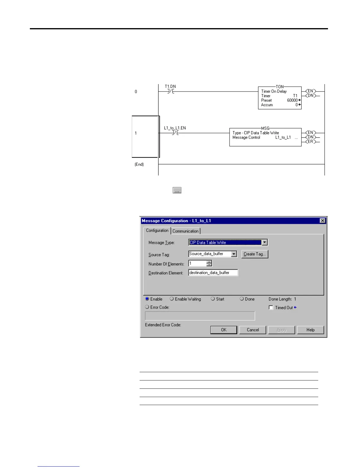
Create the Write Message Ladder Program
1. Double-click on Main Routine under the Main Program folder, and
create the following ladder program:
2. Click on the button in the MSG instruction.
The Message Configuration window will appear.
3. Under the Configuration tab, enter the following configuration:
Important:Make sure the Destination Element tag is created in the other
controller with the same name (“destination_data_buffer”) and
data type. The tag must be created under the Controller scope.
In this field Select
Message Type CIP Data Table Write
Source Tag Source_data_buffer
Number of Elements 1
Destination Element destination_data_buffer

Table of Contents

Other manuals for Allen-Bradley ControlLogix

Questions and Answers:

Question and Answer IconNeed help?

Do you have a question about the Allen-Bradley ControlLogix and is the answer not in the manual?

Allen-Bradley ControlLogix Specifications

General IconGeneral
CommunicationEtherNet/IP, ControlNet, DeviceNet, DH+
I/O CapacityUp to 128, 000 I/O points (varies by configuration)
RedundancySupported (with specific modules)
Programming SoftwareRockwell Automation Studio 5000 Logix Designer
Operating Temperature0°C to 60°C (32°F to 140°F)
Programming LanguagesLadder Logic, Function Block Diagram, Structured Text, Sequential Function Chart
ModularityYes
CertificationsUL, CE
Processor TypeMultiple options available, including standard, safety, and extreme environment processors
Power SupplyMultiple options available, including standard and redundant power supplies with various voltage ranges (e.g., 24V DC, 120/240V AC)

Related product manuals