1756-6.5.3 - December 1999
Logix5550 to Logix5550 Controller: Unscheduled Messaging 3-5
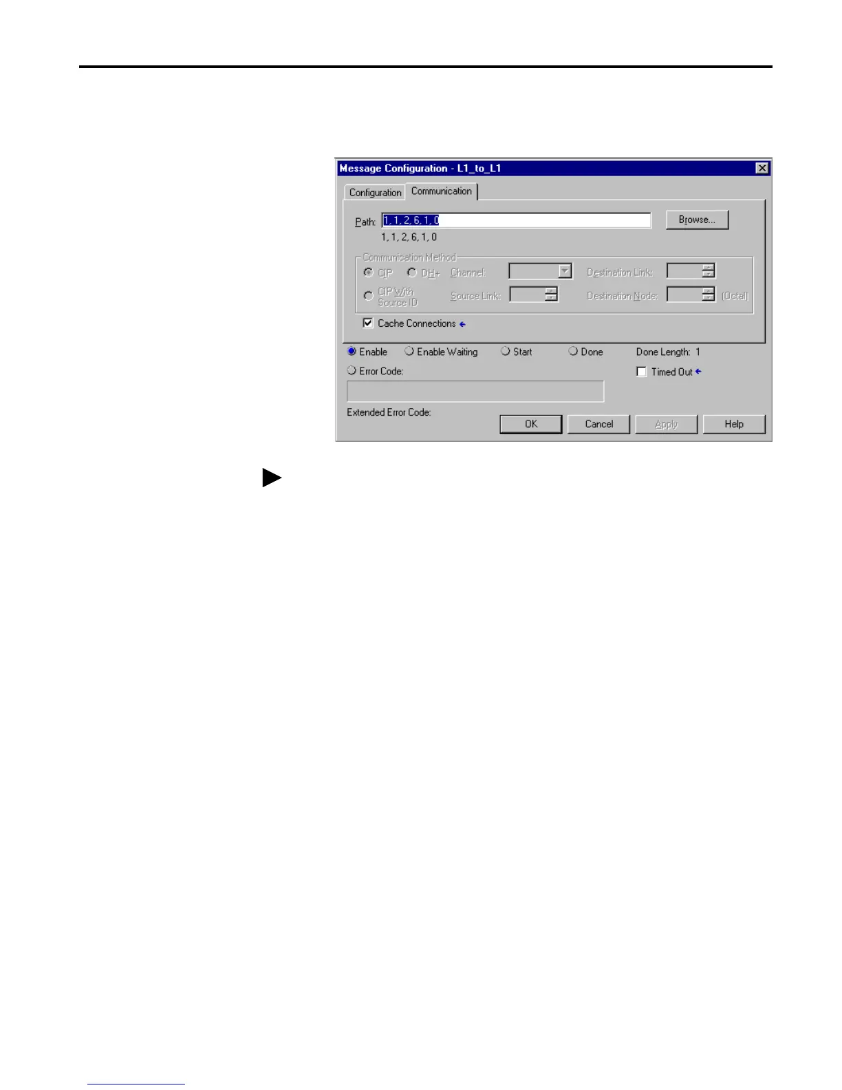
4. Select the Communication tab and enter the following path to the
destination Logix5550 controller: 1, 1, 2, 6, 1, 0.
5. Click on OK
6. Save the program.
For the path in this example:
“1” indicates a connection to the backplane of
the left ControlLogix chassis.
“1” indicates a connection to the CNB module
in slot 1.
“2” indicates a connection to port 2 of the CNB
module (get on the ControlNet wire).
“6” indicates a connection to the CNB module
at node address 6.
“1” indicates a connection to the backplane of
the right ControlLogix chassis.
“0” indicates a connection to the Logix5550
controller in slot 0.
If the Cache Connections option is selected, the controller keeps the
connection open after it completes the data transfer. The next data transfer
uses the open connection and avoids the delay required to open the
connection. If this option is not selected, the controller closes the
connection after the data transfer operation is complete. Selecting the option
results in faster data transfers, but indefinitely retains a connection. Since
the controller has a limited number of connections, this could eventually
result in the controller being unable to establish connections.

 Loading...


