EasyManuals Logo

Allen-Bradley ControlLogix User Manual

Allen-Bradley ControlLogix
203 pages
To Next Page IconTo Next Page
To Previous Page IconTo Previous Page
Page #162 background imageLoading...
Page #162 background image
1756-6.5.3 - December 1999
11-10 Adding an I/O Chassis to an Existing ControlNet Network
3. Select the Edit Tags tab at the bottom of the Controller Tags window.
4. Create the following tag:
Modify the Ladder Program
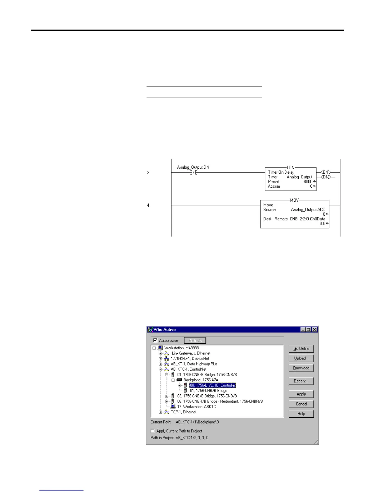
1. Double-click on Main Routine under the Main Program folder, and
add rungs 3 and 4 to the ladder program:
2. Save the program.
Download the Program
(1)
1. Click on the Communications menu and select Who Active.
2. The Who Active window will appear (Your window may look different
depending upon the drivers and other devices you have installed).
Tag Name Type
Analog_Output
Timer
(1)
This example uses RSLogix5000 version 2.25. See Appendix D if you are using version 2.10 or earlier.

Table of Contents

Other manuals for Allen-Bradley ControlLogix

Questions and Answers:

Question and Answer IconNeed help?

Do you have a question about the Allen-Bradley ControlLogix and is the answer not in the manual?

Allen-Bradley ControlLogix Specifications

General IconGeneral
CommunicationEtherNet/IP, ControlNet, DeviceNet, DH+
I/O CapacityUp to 128, 000 I/O points (varies by configuration)
RedundancySupported (with specific modules)
Programming SoftwareRockwell Automation Studio 5000 Logix Designer
Operating Temperature0°C to 60°C (32°F to 140°F)
Programming LanguagesLadder Logic, Function Block Diagram, Structured Text, Sequential Function Chart
ModularityYes
CertificationsUL, CE
Processor TypeMultiple options available, including standard, safety, and extreme environment processors
Power SupplyMultiple options available, including standard and redundant power supplies with various voltage ranges (e.g., 24V DC, 120/240V AC)

Related product manuals