1756-6.5.3 - December 1999
Installing the ControlNet Network 2-7
Important:You can install or remove a module while chassis power is
applied.
Connecting the ControlNet
Network
Connect the 1756-CNB modules and the 1784-KTCX15 communication
interface card to the ControlNet network using taps (1786-TPS, -TPYS,
-TPR, -TPYR).
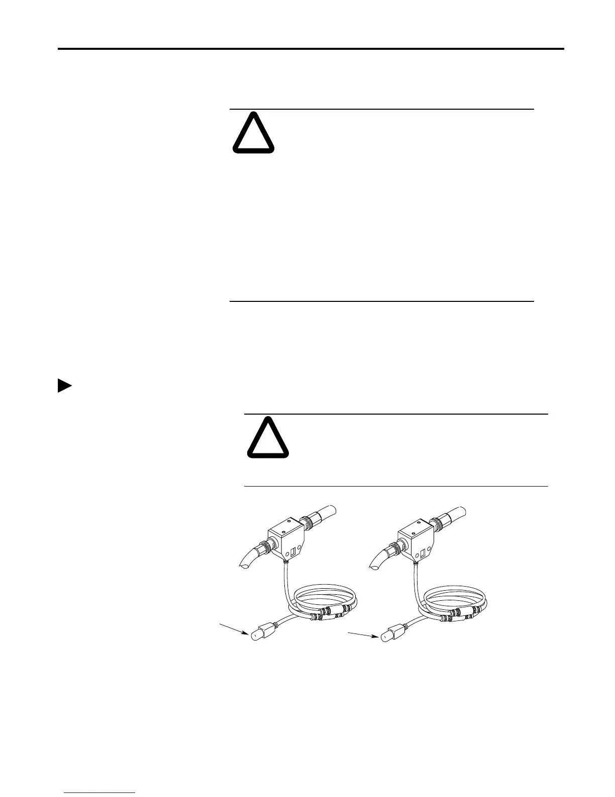
1. Remove and save the dust cap(s) from the ControlNet tap(s)
.
ATTENTION: When you insert or remove a module
while backplane power is on, an electrical arc may
occur. An electrical arc can cause personal injury or
property damage by:
• sending an erroneous signal to your system’s field
devices causing unintended machine motion or loss
of process control.
• causing an explosion in a hazardous environment.
Repeated electrical arcing causes excessive wear to
contacts on both the module and its mating connectors.
Worn contacts may create electrical resistance that can
affect module operation.
When connecting a
ControlNet network, you
should also refer to the
ControlNet Cable System
Planning and Installation
Manual, publication number
1786-6.2.1.
!
ATTENTION: Do not allow any metal portions of the
tap to contact any conductive material. If you
disconnect the tap from the module, place the dust cap
back on the connector to prevent the connector from
accidentally contacting a metallic grounded surface.
segment 1
segment 2
dust cap
dust cap
1756-CNB - segment 1
1756-CNBR - segments 1 and 2

 Loading...


