EasyManuals Logo

Allen-Bradley ControlLogix User Manual

Allen-Bradley ControlLogix
203 pages
To Next Page IconTo Next Page
To Previous Page IconTo Previous Page
Page #69 background imageLoading...
Page #69 background image
1756-6.5.3 - December 1999
Logix5550 Controller to PLC-5C: Unscheduled Messaging 5-5
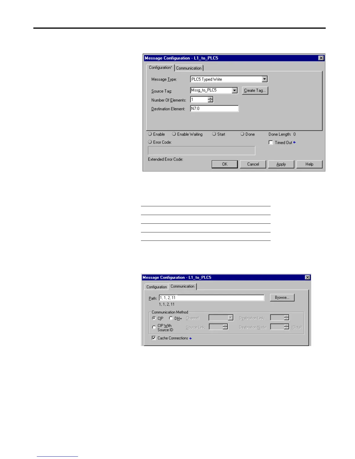
The Message Configuration window will appear.
3. Under the Configuration tab, enter the following configuration:
4. Select the Communication tab and enter the following path to the
PLC-5C on ControlNet.
5. In the Communication Method area, click on the CIP radio button.
In this field Select
Message Type PLC5 Typed Write
Source Tag Mssg_to_PLC5
Number of Elements 1
Destination Element N7:0
For the path in this example:
“1” indicates a connection to the backplane of
the ControlLogix chassis.
“1” indicates a connection to the CNB module
in slot 1.
“2” indicates a connection to port 2 of the CNB
module (get on the ControlNet wire).
“11” indicates a connection to the PLC-5C at
node 11.

Table of Contents

Other manuals for Allen-Bradley ControlLogix

Questions and Answers:

Question and Answer IconNeed help?

Do you have a question about the Allen-Bradley ControlLogix and is the answer not in the manual?

Allen-Bradley ControlLogix Specifications

General IconGeneral
CommunicationEtherNet/IP, ControlNet, DeviceNet, DH+
I/O CapacityUp to 128, 000 I/O points (varies by configuration)
RedundancySupported (with specific modules)
Programming SoftwareRockwell Automation Studio 5000 Logix Designer
Operating Temperature0°C to 60°C (32°F to 140°F)
Programming LanguagesLadder Logic, Function Block Diagram, Structured Text, Sequential Function Chart
ModularityYes
CertificationsUL, CE
Processor TypeMultiple options available, including standard, safety, and extreme environment processors
Power SupplyMultiple options available, including standard and redundant power supplies with various voltage ranges (e.g., 24V DC, 120/240V AC)

Related product manuals