5Serial Ports
5 – 19
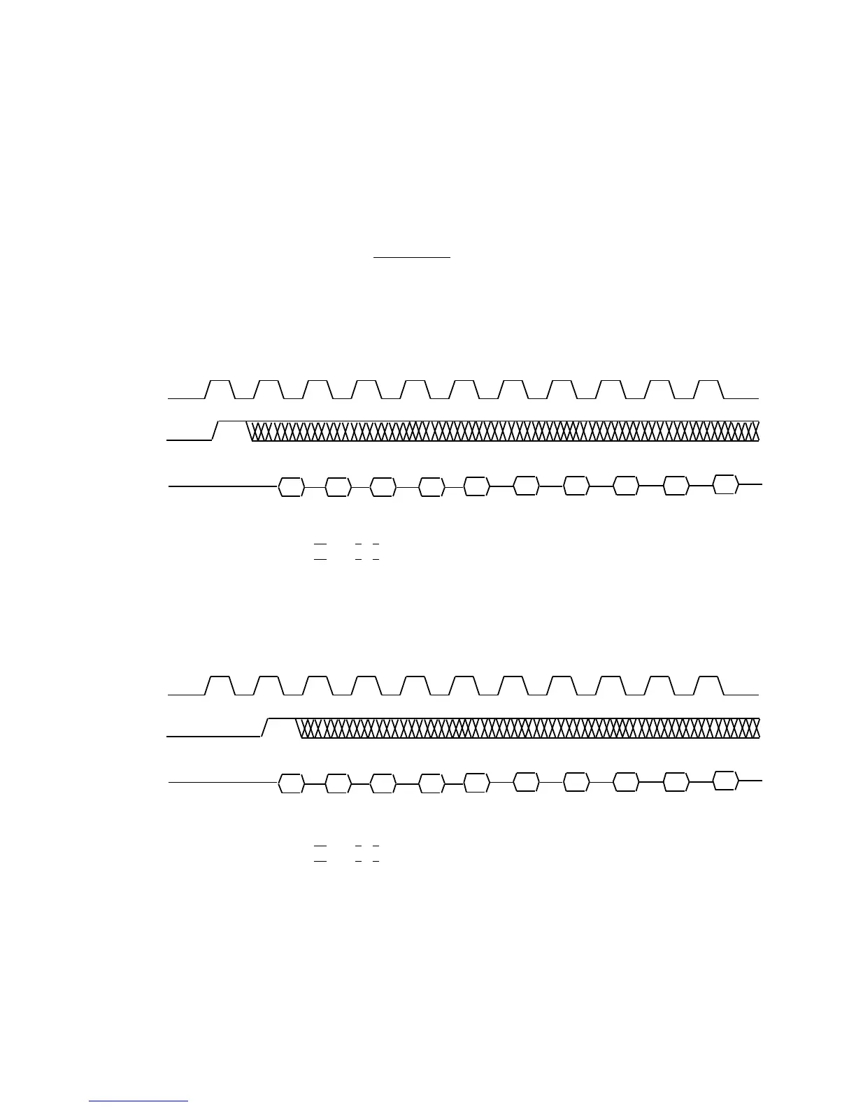
SCLK
RFS
DR
B3 B2 B1 B0 B3 B2 B1 B0 B2B3
SCLK
RFS
DR
B3 B2 B1 B0 B3 B2 B1 B0 B2B3
= low, and X can be either. The underlined bit values are the bits which
set the modes illustrated in the example.
Figures 5.10 to 5.15 show framing for receiving data. In Figures 5.10 and
5.11, the normal framing mode is shown for noncontinuous data (any
number of SCLK cycles between words) and continuous data (no SCLK
cycles between words). Figures 5.12 and 5.13 show noncontinuous and
SPORT Control Register:
Internal Frame Sync 0X0
0 XXX1 X0XX 0011
External Frame Sync 0X00 XXX0 X0XX 0011
Figure 5.14 SPORT Receive, Unframed Mode, Normal Framing
SPORT Control Register:
Internal Frame Sync 0X01 XXX1 X0XX 0011
External Frame Sync 0X01 XXX0 X0XX 0011
Figure 5.15 SPORT Receive, Unframed Mode, Alternate Framing

 Loading...

