10Memory Interface
10 – 33
Control Register and the IOWAIT0-3 bit fields that control I/O memory
waitstate regions.
The Wait State Control Register is divided into the following fields:
• IOWAIT0. This 3-bit field sets the number of waitstates (0-7) for
accesses to I/O memory addresses 0x000–0x1FF.
• IOWAIT1. This 3-bit field sets the number of waitstates (0-7) for
accesses to I/O memory addresses 0x200–0x3FF.
• IOWAIT2. This 3-bit field sets the number of waitstates (0-7) for
accesses to I/O memory addresses 0x400–0x5FF.
• IOWAIT3. This 3-bit field sets the number of waitstates (0-7) for
accesses to I/O memory addresses 0x600–0x7FF.
• DWAIT. This 3-bit field sets the number of waitstates (0-7) for accesses
to external program and data memory overlays.
Note: The PWAIT field of the System Control Register sets the number of
waitstates for access to external program memory overlays.
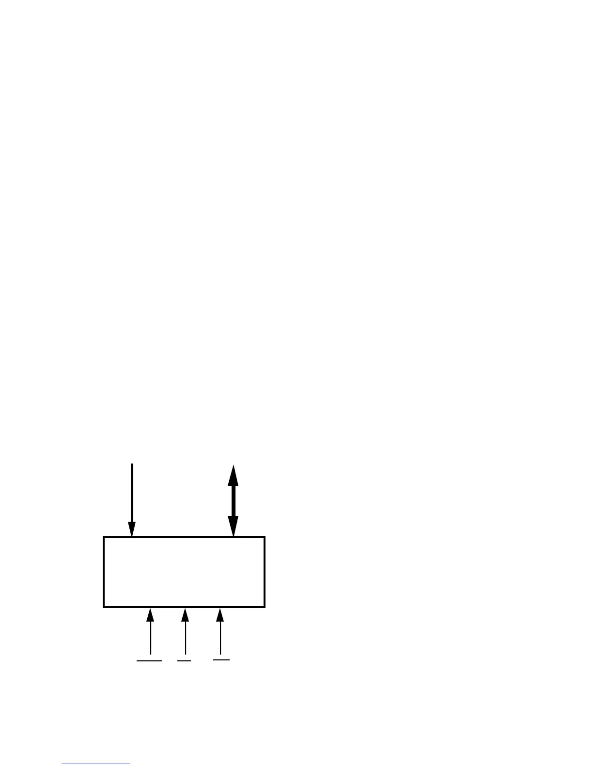
When you connect a parallel I/O device to the ADSP-2181 as shown in
Figure 10.31 I/O Memory Space Peripheral Connection Example
IOMS RD
WR
DATA 23:8
ADDRESS 10:0
or
Decoded
Address Input
Codec, A/D, D/A, or
other peripheral device.

 Loading...

