10 Memory Interface
10 – 34
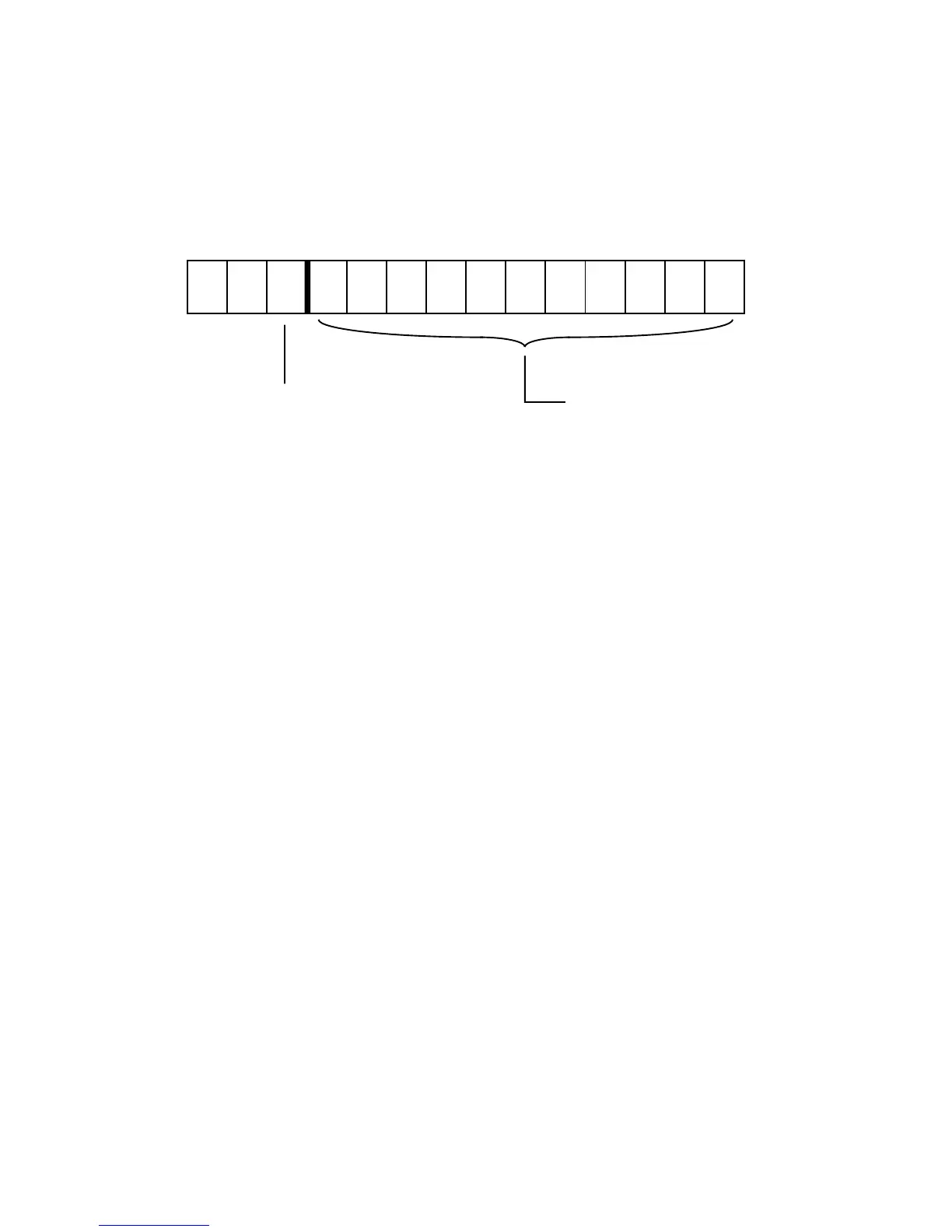
1312111098 76 54 3210
00x10
I/O Memory Address
00000
I/O Memory Operation
1 = Write
0 = Read
0000
Figure 10.32 I/O Memory Address Word
Figure 10.31, the address sent to the device appears on the external
address bus as shown in Figure 10.32.
Host interfaces can use the additional communications channel provided
by the ADSP-2181’s I/O memory space. If your system bus interface ASIC
uses a set of data registers for passing control information from the system
bus and must also pass large amounts of sample data, map the control
registers as I/O memory peripherals and transfer the sample data using
IDMA. This combination of the I/O memory and IDMA channels reduces
system bus transfer rate limitations.
Note: As with other ADSP-2100 Family processors, on the ADSP-2181 you
can define memory-mapped I/O ports with the assembler’s .PORT
directive. On the ADSP-2181, this directive defines memory-mapped I/O
ports in external program memory overlays or data memory overlays. If
you want to use this feature, you must make sure at runtime that you are
on the correct program memory overlay or data memory overlay when
accessing the port; the assembler and linker will not flag errors in .PORT
accesses related to overlays because the issue is resolved at runtime. The
“IO” keyword does not work with the .PORT directive; to assign symbolic

 Loading...

