5-6 ISDB-T SFN Verification, Option 32 Option Verification
5-22 PN: 10580-00255 Rev. J MT8212E and MT8213E MM
36. Press the Frequency/Level main menu key and set the Reference Level of the MT821xE to –15 dBm.
37. After the Measuring percentage gets to 100%, record the –15 dBm Channel Power from the MT821xE to
the M(Level) column under Pre Amp Off in Table A-32.
38. Calculate the Deviation using the following formula:
Deviation = M(Level) – SB(–10) – ΔAB(–10) – AT(–10) + AT(set)
39. Record the result into the Dev column under Pre Amp Off in Table A-32 and verify that it is within
specification.
40. Set the MN63A attenuation to the next AT(set) value in Table A-32.
41. Set the Reference Level of the MT821xE to –20 dBm.
42. After the Measuring percentage gets to 100%, record the –20 dBm Channel Power from the MT821xE
into the M(Level) column under Pre Amp Off in Table A-32.
43. Calculate the Deviation using the following formula:
Deviation = M(Level) – SB(–10) – ΔAB(–10) – AT(–10) + AT(set)
44. Record the result to the Dev column under Pre Amp Off in Table A-32 and verify that it is within
specification.
45. Press the Frequency/Level main menu key and set Pre Amp to On. Change Reference Level if required.
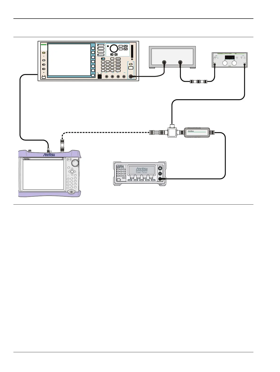
Figure 5-5. ISDB-T SFN Level Accuracy and 1 dB Compression Level Post-test Setup
MT821xE Cell Master
Power Charge
+/-
.
0
3
Sweep
2
Calibrate
1
Preset
6
Limit
5
Trace
4
Measure
9
Mode
8
System
7
File
Shift
Back
Enter
ESC
CellMaster
MT8212E
Function
Ethernet Control Input Modulation Input
Cursor/Edit
RF Output
3
MG3700
Vector Signal
Generator
250kHz-6GHz
3
From: MG3700A 10 MHz Out
To: MT821xE Ext Trigger In
ML2438A Power Meter
MA2482D
Sensor B
1870A
Power Splitter
MG3700A
RF Power Amplifier
MN63A
44-10
1N50C
34NN50A