5-7 GSM/GPRS/EDGE Signal Analyzer Verification, Options 40 and 41 Option Verification
5-26 PN: 10580-00255 Rev. J MT8212E and MT8213E MM
Setup
Procedure
1. Calibrate the power sensor prior to connecting to the power splitter.
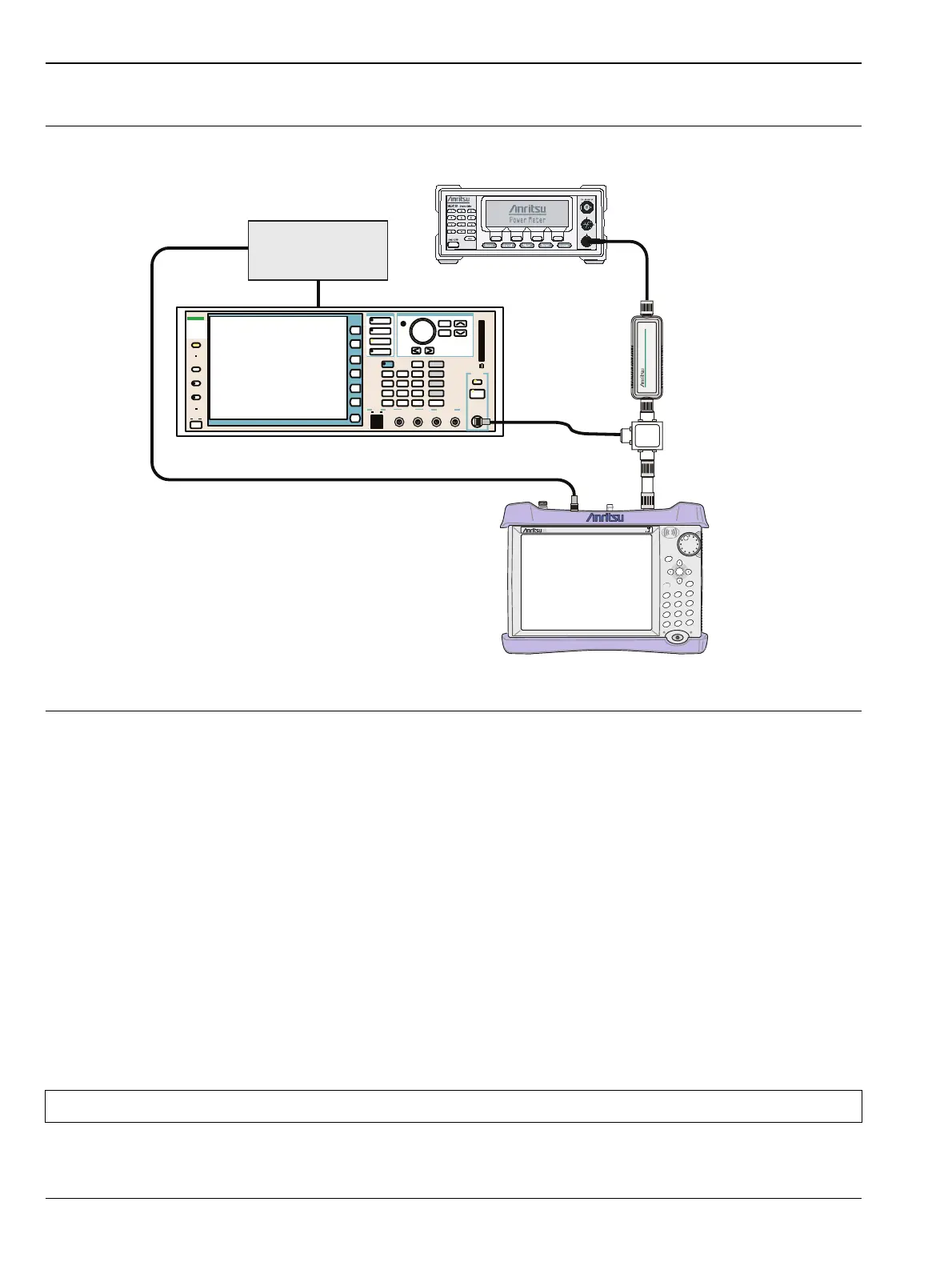
2. Connect the equipment as shown in Figure 5-6.
3. On the power meter, press the Sensor key, the Cal Factor soft key, and then the FREQ soft key. Use the
keypad to enter 850 MHz as the input signal frequency, which sets the power meter to the proper power
sensor calibration factor. Press the System key to display the power reading.
4. On the power meter, press the Sensor key, the Setup soft key, and then the MODE soft key until
Measurement MODE is Mod average. Press the System key to display the power reading.
5. Set the MT821xE mode to GSM/GPRS/EDGE Signal Analyzer. Press Shift and press Preset (1) to
preset the MT821xE.
6. On the MG3700A, press the Preset key (Yellow key on the upper left hand side).
7. Press the Down Arrow key or turn the knob to select Yes.
8. Press the Set key.
9. Press the (F1) soft key to select Load File to Memory.
Figure 5-6. GSM/EDGE Signal Analyzer Option Verification
Note The MG3700A has two Set keys, and they both have the same function.
MT821xE Cell Master
Power Charge
+/-
.
0
3
Sweep
2
Calibrate
1
Preset
6
Limit
5
Trace
4
Measure
9
Mode
8
System
7
File
Shift
Back
Enter
ESC
CellMaster
MT8212E
MG3700A Vector Signal Generator
Function
Ethernet
Control Input
Modulation Input
Cursor/Edit
RF Output
3
MG3700
Vector Signal
Generator
250kHz-6GHz
10 MHz
Reference
ML2438A Power Meter
MA2482D
Power Sensor
1870A
Power Splitter