CPS100 SERIES OPERATION MANUAL
SECTION 5:
Unpacking and Installation
Entire Contents Copyright 2018 by Adaptive Power Systems, Inc. (APS) • All Rights Reserved • No reproduction without written authorization from APS.
APS CPS100 Series Power Source Operation Manual Page 52 of 231
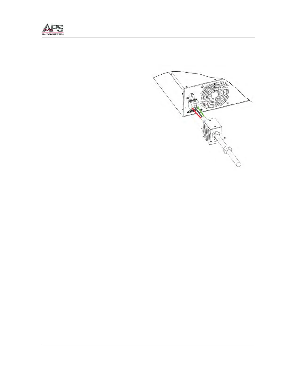
5.8.6 Output Power Cord Connection
To install a power cord to the output terminal block, proceed as follows:
1. Strip the outside installation of
the AC power cord
approximately 25 mm or 1 inch.
Then strip 7 mm or 1/3 inch of
insulation from each of the wires
(L, N, G) of the power cord.
2. Loosen the plastic nut of the
provided output safety cover’s
stain relief.
3. Pass the cable end including the
line, neutral and ground wire
through the cable strain relief as
illustrated in the adjacent
drawing.
4. Insert each lead in its
corresponding output terminal
position as shown.
5. Using a suitable size flat blade screwdriver, tighten the terminal block screws
assuring all wires are held tightly.
6. Replace and faster the safety cover and tighten the plastic nut of the strain relief
clamp.
5.8.7 Connecting a UUT
When setting up for a new test and connecting any equipment to the power source,
proceed as follows:
1. Always make sure the power source is turned OFF at the POWER switch when
making any output connections.
2. Check that the output of the equipment under test is OFF and that the load is not
still energized. This applies in particular to DC Mode when driving a load with input
capacitance or batteries.
3. Connect the power cord leads to the unit under test.
4. Check the polarity of the connections and connect the other end of the load wires to
the input terminals of the equipment under test.