CPS100 SERIES OPERATION MANUAL
SECTION 5:
Unpacking and Installation
Entire Contents Copyright 2018 by Adaptive Power Systems, Inc. (APS) • All Rights Reserved • No reproduction without written authorization from APS.
APS CPS100 Series Power Source Operation Manual Page 61 of 231
5.10.5 GPIB Interface (Option on all CPS Models)
GPIB connection is via a 24pin IEEE-488 Centronics connector on the rear panel of the unit.
This interface option allows the unit to be connected to a GPIB controller and other GPIB
devices. A GPIB system can be connected in any configuration (star, linear, or both) as long
as the following conditions are met:
• The maximum number of devices including the controller is equal or less than 15.
• The maximum length of the GPIB cable is no more than 2 meters.
• The total lead length of all devices connected together totals less than 20 meters.
• Please make sure the lock screws are firmly hand-tightened, use a screwdriver only
for the removal of screws.
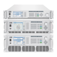
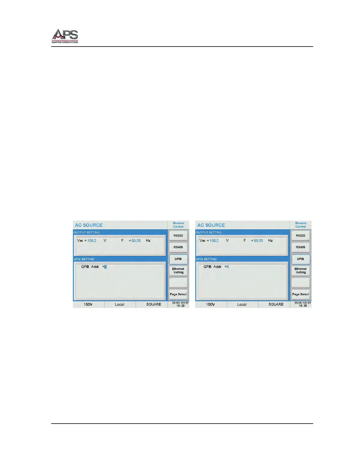
Each device on the GPIB (IEEE-488) interface must have a unique address. You can set the
address of the CPS series to any value between 1 and 30. The address can only be set from
the front panel. The address is stored in non- volatile memory and does not change when
the power has been off or after a remote reset.
Note: The available address range is 1 ~ 30.
GPIB interface settings can be configured from the “CONFIG MENU” by selecting “Remote
Control”, then “GPIB”. See section 6.8.1.1, “Remote Control” on page 85 for details.
Scroll to the GPIB Addr field and use the shuttle to set the desired address.