CPS100 SERIES OPERATION MANUAL
SECTION 5:
Unpacking and Installation
Entire Contents Copyright 2018 by Adaptive Power Systems, Inc. (APS) • All Rights Reserved • No reproduction without written authorization from APS.
APS CPS100 Series Power Source Operation Manual Page 53 of 231
5.8.8 Remote Voltage Sense
The power source senses its own output voltage and adjusts as needed to maintain the set
voltage regardless of load changes. Voltage sense is supported in two ways:
Local (internal): Voltage sense is done at the output terminals of the power source
by looping a sense wire jumper from the external sense input to a
set of output terminals on the same connector that are internally
connected to the output terminals.
Remote (external): Remote voltage sensing allows the power source to compensate for
any voltage drop between the source’s output terminal and the load
connection point caused by the wire impedance of the load wires.
This voltage drop can be significant if the length of the load wires is
long and/or the wire gauge is marginal. This voltage drop will also
increase with the amount of load current.
To overcome this, the power source can sense at the load terminals using the external
voltage sense connector. The sense wires will not carry any load current as the Vsense input
is high impedance to normal 24AWG wire can be used for the external sense connection.
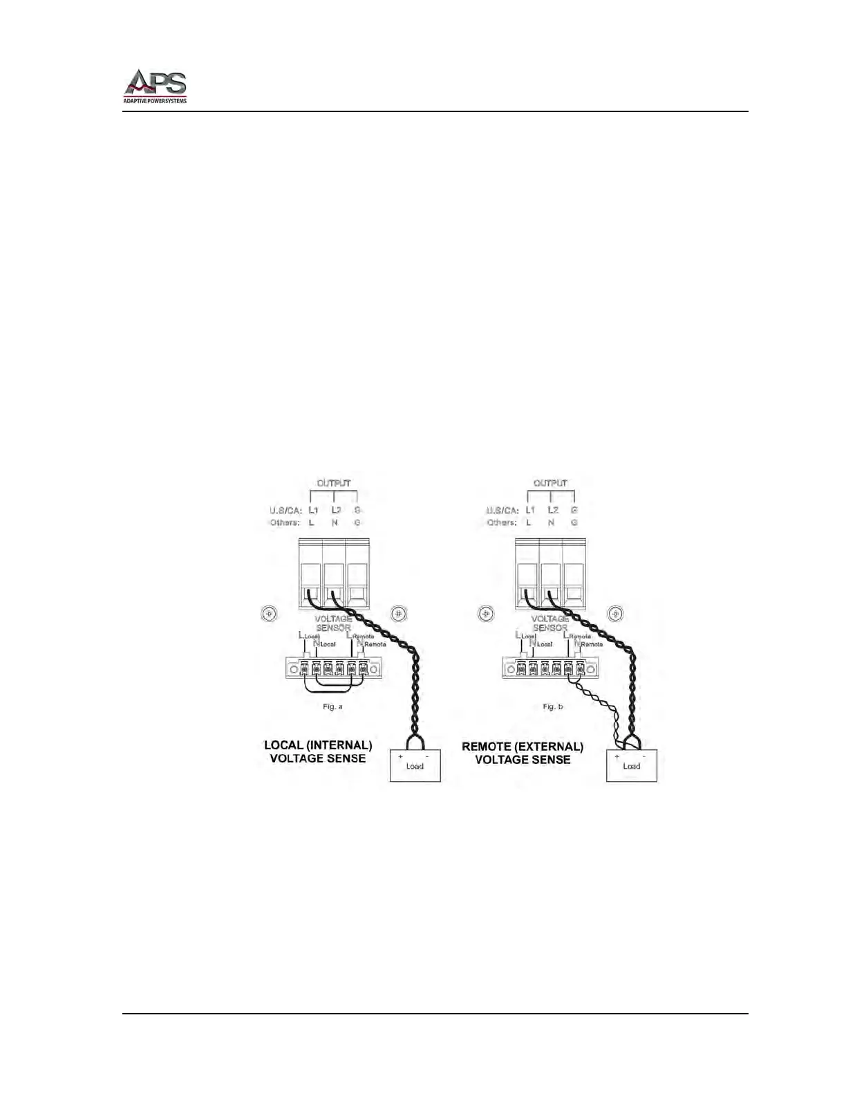
Figure 5-7: Voltage Sense Connections
For internal voltage sense, jumper the VOLTAGE SENSOR connector as shown in Figure 5-7 a.
This will connect the output of the power source to the sense inputs. Make sure the sense
wire jumpers are NOT crossed. L to L and N to N.
For external voltage sense, remove the jumper from the VOLTAGE SENSOR connector and
connect a twisted pair of wire long enough to reach the point of load connection as shown
in Figure 5-7 b. This will voltage present at the load to the sense inputs. Make sure the sense
wire jumpers are NOT crossed. L to L and N to N.