CPS100 SERIES OPERATION MANUAL
SECTION 5:
Unpacking and Installation
Entire Contents Copyright 2018 by Adaptive Power Systems, Inc. (APS) • All Rights Reserved • No reproduction without written authorization from APS.
APS CPS100 Series Power Source Operation Manual Page 65 of 231
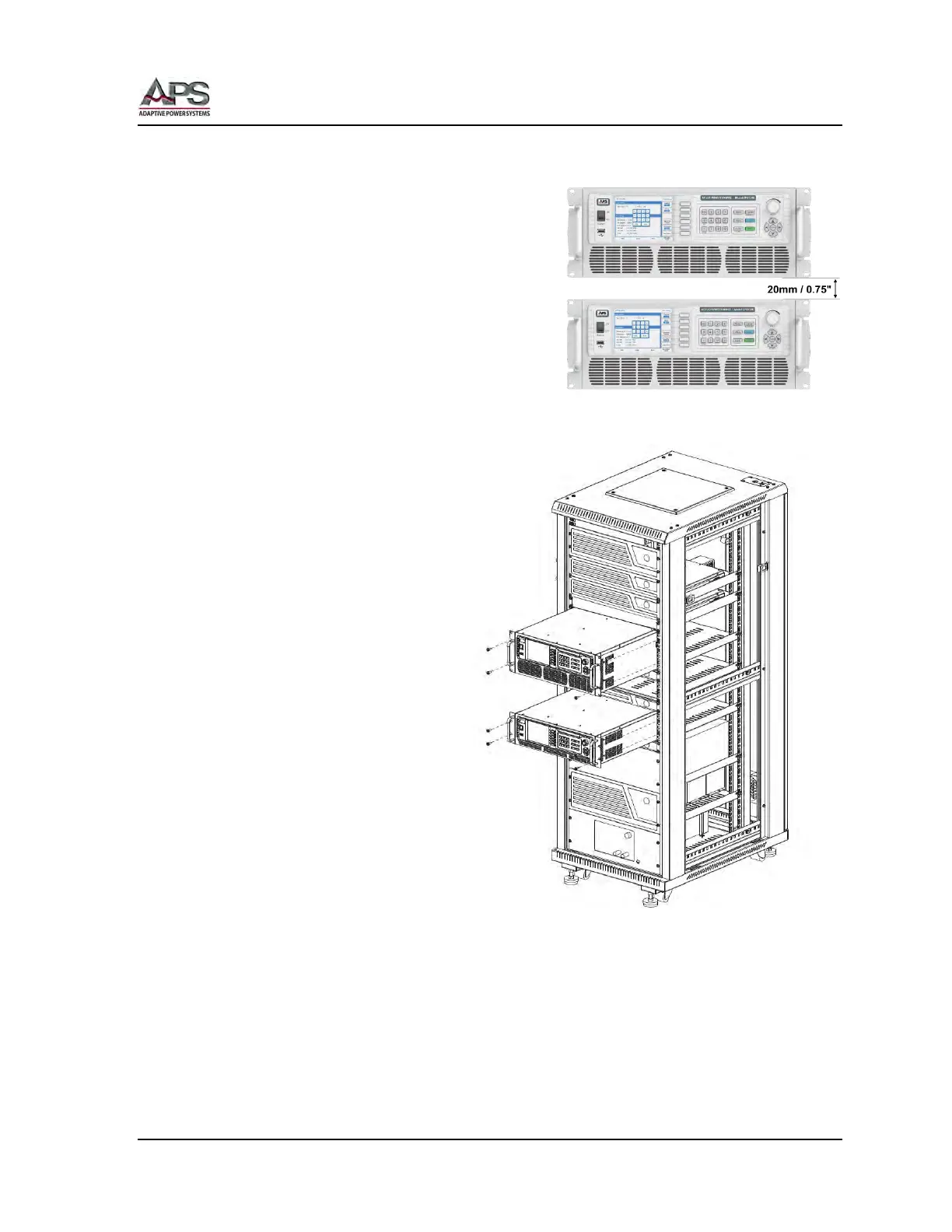
5.2.2 Rack Installation
The power source must be supported by either a
19” shelf or L-brackets of sufficient width rated
for more than the weight of the unit.
To allow sufficient cooling for each unit, leave at
least 20 mm or 0.75” of space between 2 or more
units or between units and other equipment as
shown to the right. This allows sufficient air to
move between units to provide additional
convection cooling.
Secure each unit to the front mounting strip of
the cabinet using at least two screws on each
side.
Note: These screws are not
included in the ship kit of the CPS100
Series.
Figure 5-16: Cabinet Installation Drawing