CPS100 SERIES OPERATION MANUAL
SECTION 6:
Front Panel Operation
Entire Contents Copyright 2018 by Adaptive Power Systems, Inc. (APS) • All Rights Reserved • No reproduction without written authorization from APS.
APS CPS100 Series Power Source Operation Manual Page 102 of 231
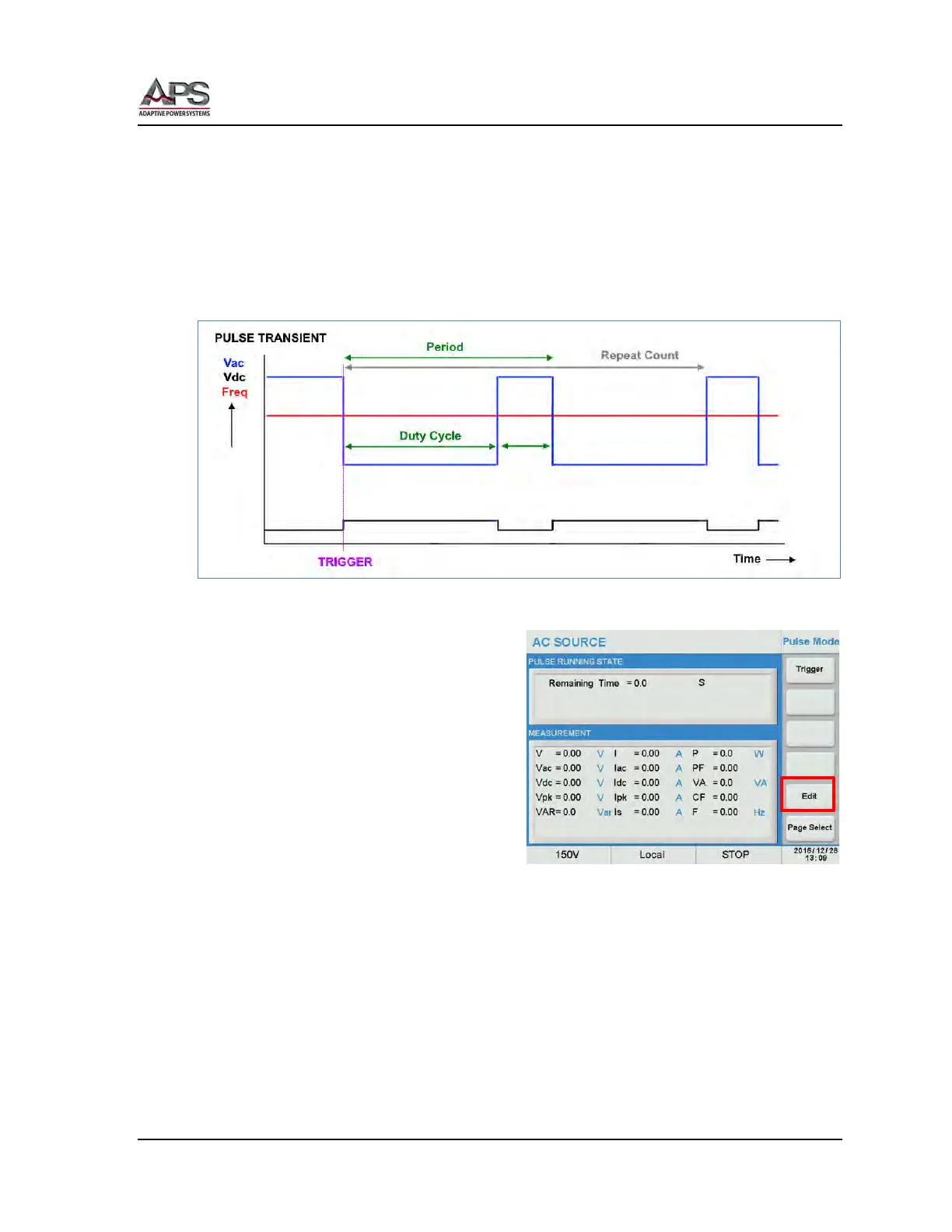
6.9.1.2 Pulse Transient Mode
The Pulse mode of operation allows repetitive output level changes between two different
set values to be implemented easily. These alternative values can be repeat and the duty
cycle can be set anywhere from 1% to 99%.
The output change occurs when the transient trigger is generated, either from the front
panel or through some other means. The principle behind a step transient is illustrated
below.
Figure 6-8: Illustration of a PULE Transient
The PULSE transient is accessed by pressing
the [Pulse] soft key in the PLD screen. To
create an new or edit an existing PULSE
transient, press the [Edit] soft key to enter
Edit mode.
A Pulse transient definition includes the
following parameters:
• Vac Step value for Vac
• Vdc start Step value for Vdc
• F Step value for
Frequency
• Duty Cycle Duty cycle in % of period
at Step Value
• Degree Phase Angle from 0.0° ~ 359.9°
• Waveform Waveform Group A or B
• Period Duration time
• Count Repeat Count 0 ~ 9999. . A zero repeat count indicates infinite
looping.
• Start The time period to hold the present output set values before
starting the pulse period(s).