CPS100 SERIES OPERATION MANUAL
SECTION 5:
Unpacking and Installation
Entire Contents Copyright 2018 by Adaptive Power Systems, Inc. (APS) • All Rights Reserved • No reproduction without written authorization from APS.
APS CPS100 Series Power Source Operation Manual Page 58 of 231
Remote Control Programming Interfaces
The CPS100 Series offers standard RS232, RS485 and USB interfaces for remote control
operation. CPS100 models of 2000VA and higher also offer standard Ethernet (LAN).
Other interfaces may be specified at the time of order as they are installed at the factory
prior to shipment. It is possible to add interface options in the field. Available interface
options are:
For CPS106, CPS110 and CPS115 models:
• Ethernet / LAN + GPIB (Option –LAN+GPIB)
Note: This interface option installs in place of the standard RS232, RS484 and USB
interfaces. (Occupies the same physical slot).
Figure 5-12: CPS106, CPS110 or CPS115 rear panel with optional LAN+GPIB Interfaces
For CPS120, CPS130, CPS140 and CP150 models:
• GPIB / IEEE-488 (Option –GPIB)
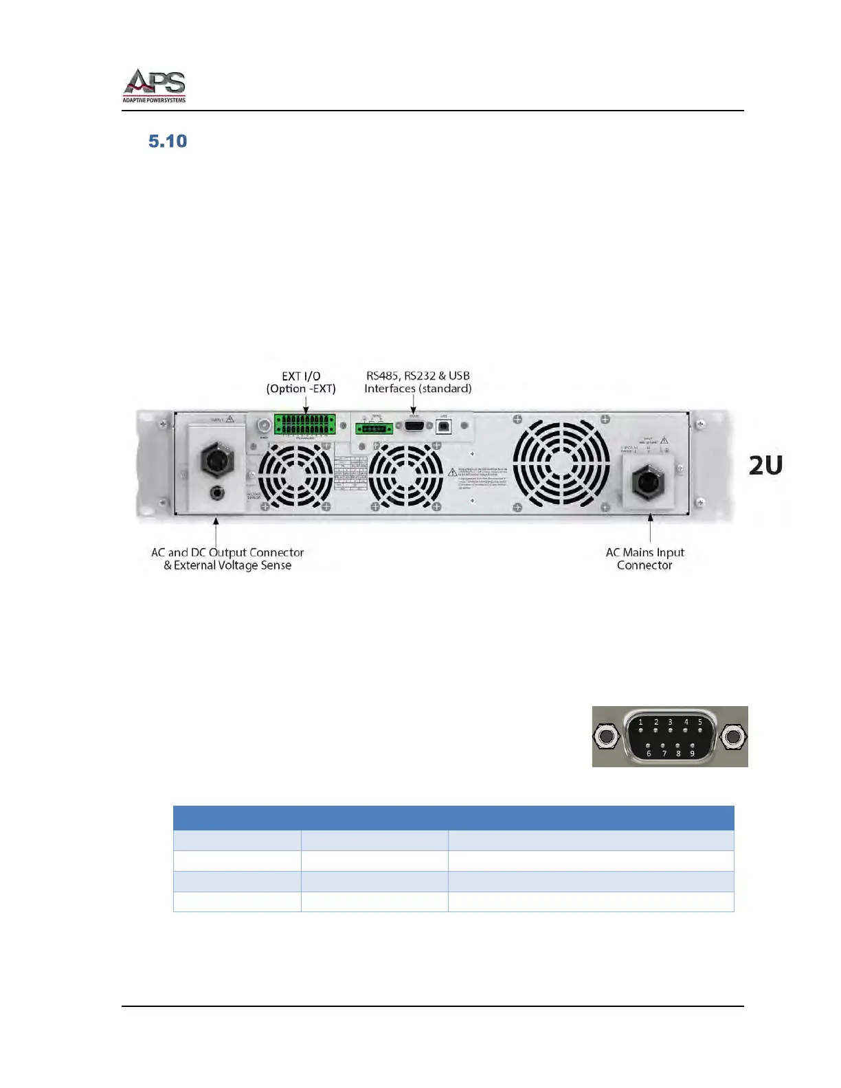
5.10.1 RS232 Serial Interface
Figure 5-13 shows the RS232 connector (Male) on the rear panel.
This connects the power source to an RS232 port of a computer.
Signal Pin Assignments:
Figure 5-13: RS232 Connector
Table 5-6: RS232 DB9 Pin Assignments