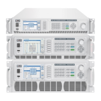
CPS100 SERIES OPERATION MANUAL
SECTION 5:
Unpacking and Installation
Entire Contents Copyright 2018 by Adaptive Power Systems, Inc. (APS) • All Rights Reserved • No reproduction without written authorization from APS.
APS CPS100 Series Power Source Operation Manual Page 57 of 231
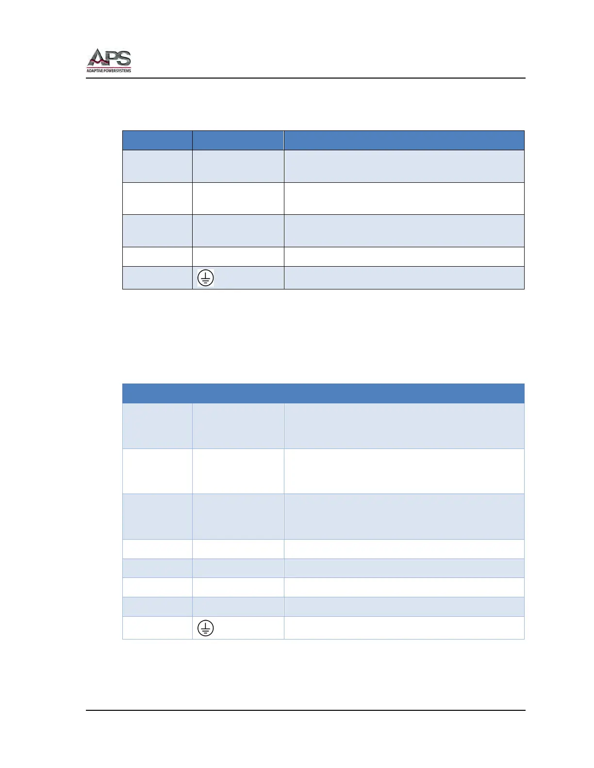
5.9.6 AUX I/O Card Pin Assignments
Analog I/O Relay Contacts
Pin # Signal Description
1, 2 RELAY 1, PASS
These two pins will be shorted internally when a test
mode has a PASS result.
3, 4 RELAY 2, FAIL
These two pins will be shorted internally when a test
mode has a FAIL result.
5, 6 RELAY 3, RUN
These two pins will be shorted internally when a test
is running.
7, 8 RELAY 4 Not Used
9, 10
Chassis Ground
Table 5-4: AUX I/O Analog Pin Functions
TTL Digital Inputs
For all TTL inputs, logic voltage levels are:
• Logic Low = 0V ~ 0.5V
• Logic High = 4.5 ~ 5.5V
Pin # Signal Description
1 ON/OFF
Output control input.
Low = Output OFF
High = Output ON
2 KEEP OFF
OUTPUT lockout input.
Low = Output Control Disabled
High = Output Control Enabled
3 RESET
Unit Reset input.
Low = Reset Active
High = Reset Inactive
4 RECALL 1 Setup Recall No: LSB, Bit 0: Low or High
5 RECALL 2 Setup Recall No: Bit 1: Low or High
6 RECALL 3 Setup Recall No: MSB, Bit 2: Low or High
7 N/A Not Used
8, 9, 10
Chassis Ground
Table 5-5: AUX I/O Digital Input Pin Functions