CPS100 SERIES OPERATION MANUAL
SECTION 6:
Front Panel Operation
Entire Contents Copyright 2018 by Adaptive Power Systems, Inc. (APS) • All Rights Reserved • No reproduction without written authorization from APS.
APS CPS100 Series Power Source Operation Manual Page 68 of 231
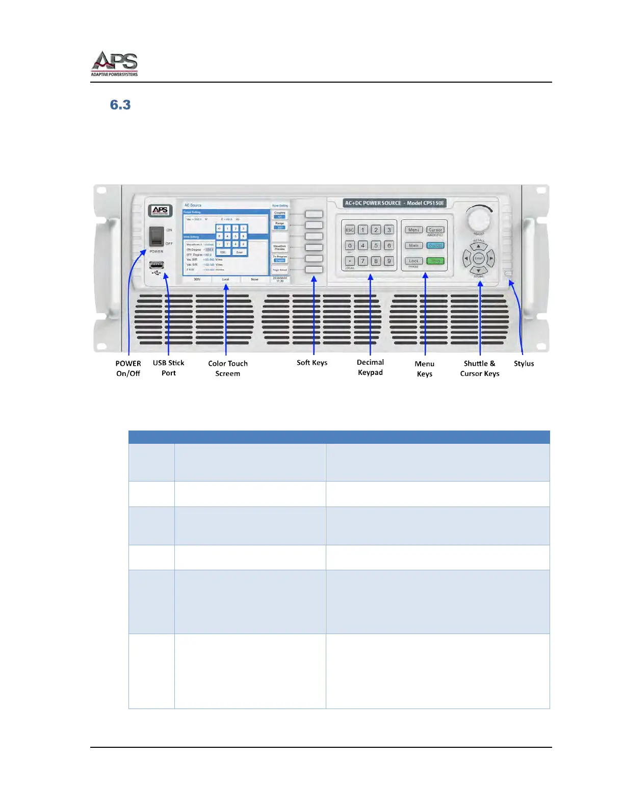
Front Panel Layout
The front panel layout is shown in Figure 6-2 below. Operation is accomplished by using a
combination of on-screen touch controls, function keys, a decimal keypad, a small grouping
of menu keys and a shuttle knob and cursor pad combination.
The front panel control sections are shown in the image below.
Figure 6-2: CPS100 Series Front Panel Displays and Controls
The following controls and indicators are available for use.
Turns AC input power to the unit on or off. The ON
position is marked “|”. The OFF position is marker
Used to store, retrieve setups or screen captures to
a USB thumb drive.
Color LCD Touch Sensitive Display
Displays all settings, measurements and messages.
Also used to select soft keys, drop down list entries
of number or name entries.
Soft Keys change function depending on the menu
and parameter selected.
Keys 0 through 9 allow direct entry of parameter
values. The decimal point key allows entry of
fractional values. The +/- Key allows entering of
negative DC voltage values.
← ESC key backs up to previous screen or entry.
This section has six fixed function keys:
Menu Selects Function Setting Menu
Main Selects Main Menu
Lock Locks out front panel controls
Cursor Selects value field or menu. Also saves
LCD screen image to USB drive if