CPS100 SERIES OPERATION MANUAL
SECTION 5:
Unpacking and Installation
Entire Contents Copyright 2018 by Adaptive Power Systems, Inc. (APS) • All Rights Reserved • No reproduction without written authorization from APS.
APS CPS100 Series Power Source Operation Manual Page 59 of 231
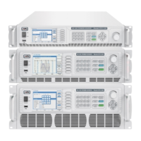
RS232 interface settings can be configured from the “CONFIG MENU” by selecting “Remote
Control”, then “RS232”. See section 6.8.1.1, “Remote Control” on page 85 for details.
Scroll through Baud rate, parity and Stop bits fields and use the shuttle to set the desired
values.
Note: This interface does not support XON/XOFF protocol or any hardware handshaking.
The controller should be configured to ignore the Handshaking Lines DTR (PIN 4),
DSR (PIN 6) and RTS (PIN 9). If the port cannot be configured through software to
ignore the lines, the handshaking lines should then be jumped together in two
different pairs. Both pins 4 & 6 and pins 7 & 8 must be jumpered together at the
controller end of the cable.
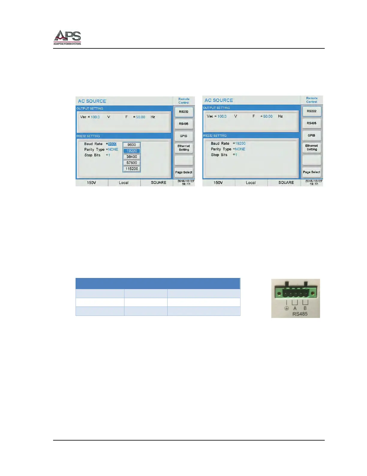
5.10.2 RS485 Serial Interface
Figure 5-13 shows the RS485 connector (Male) on the rear panel. This connects the power
source to an RS485 port of a computer.
RS485 interface settings can be configured from the “CONFIG MENU” by selecting “Remote
Control”, then “RS485”.
Scroll through Baud rate, parity, Stop bits and Address fields and use the shuttle to set the
desired values. See section 6.8.1.1, “Remote Control” on page 85 for details.