CPS100 SERIES OPERATION MANUAL
SECTION 5:
Unpacking and Installation
Entire Contents Copyright 2018 by Adaptive Power Systems, Inc. (APS) • All Rights Reserved • No reproduction without written authorization from APS.
APS CPS100 Series Power Source Operation Manual Page 56 of 231
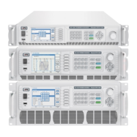
5.9.4 AUX I/O Card Connectors (CPS120 ~ CPS150 Models)
All CPS100 Series models with either a 3U or 4U height chassis support the optional AUX I/O
card.
This card contains the following connectors:
Interface Description
SYNC Sync Input BNC connector for external analog signal to control
waveform amplitude.
CAN-R Parallel Operation mode interconnect bus.
SYSTEM BUS System interface bus for communication between master and
slaves in serial, parallel or three phase configurations.
TTL / ANALOG TTL Relay Contacts / Analog
Figure 5-11: AUX I/O Option Card Connections
The following pins are available on the TTL/ANALOG Connector of the AUX I/O Option card.
ANALOG I/O – OUTPUTS - RELAY CONTACTS
TTL 1 2 3 4 5 6 7 8 9 10
DIGITAL I/O – TTL INPUTS
Note: Pins 4~6 binary input to recall setup 1 through 7.
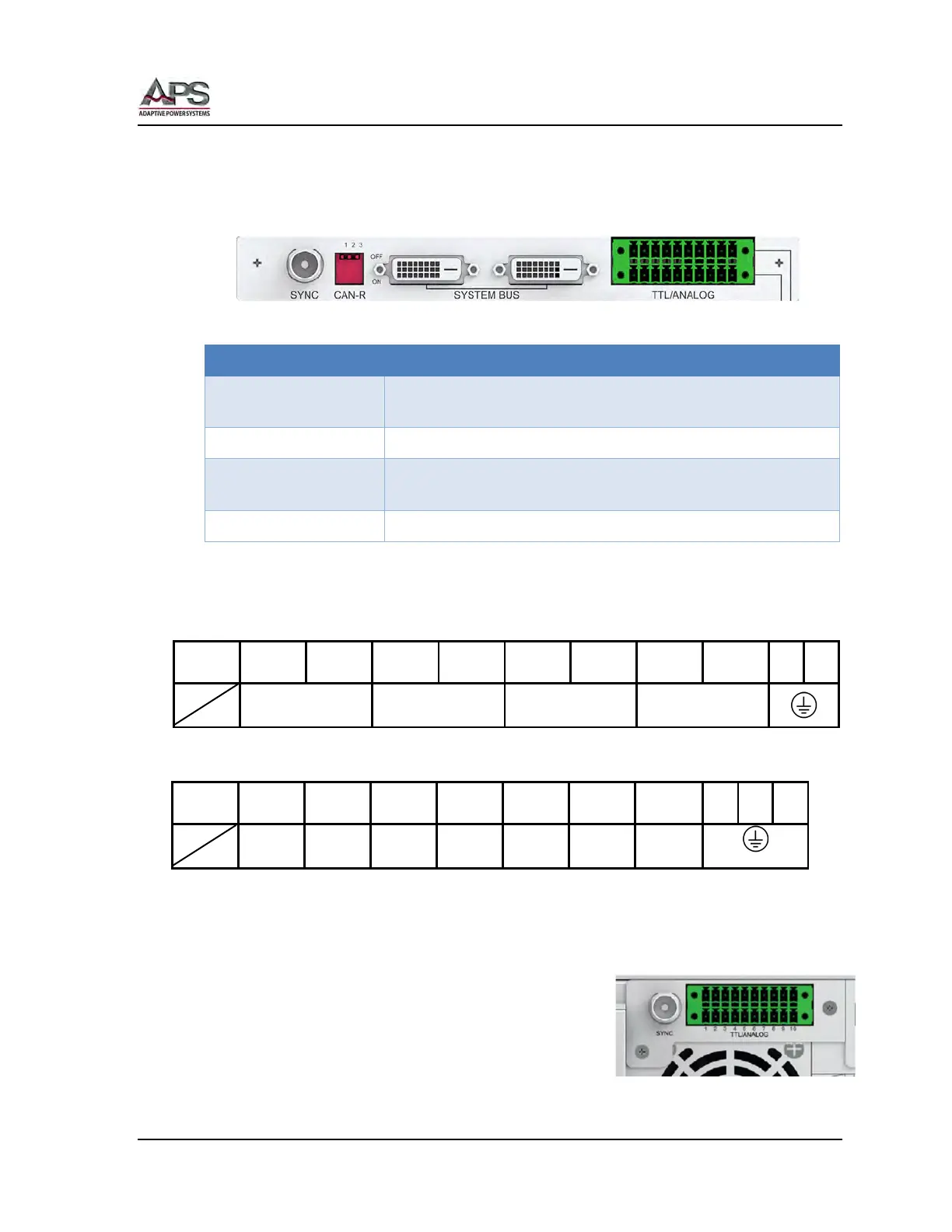
5.9.5 EXT I/O Card Connectors (CPS106, CPS110 & CPS115 Models)
The –EXT option card on 2U CPS models uses the same
connectors and pinouts as the AUX I/O option card for 3U
and 4U models. Refer to previous section for pin
configurations,
EXT. V 1 2 3 4 5 6 7 8 9 10