CPS100 SERIES OPERATION MANUAL
SECTION 6:
Front Panel Operation
Entire Contents Copyright 2018 by Adaptive Power Systems, Inc. (APS) • All Rights Reserved • No reproduction without written authorization from APS.
APS CPS100 Series Power Source Operation Manual Page 104 of 231
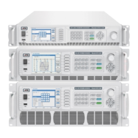
6.9.1.3 Step Transient Mode
The step mode allows the output state to transition from its present setting to a new output
state using one or more discrete voltage and or frequency steps. This represents a STEP
function as long as at least one of the parameters in the STEP differs from the present value.
The output change occurs when the transient trigger is generated, either from the front
panel or through some other means.
The principle behind a step transient is illustrated below.
Figure 6-9: Illustration of a STEP Transient
A STEP transient requires the least number
of parameters to define. The required
parameters are:
• Vac Start value for Vac
• δVac Vac step value
• Vdc Start value for Vdc
• δVdc Vdc step value
• F Start value for
Frequency
• δF F step value
• Deg. Phase Angle from
0.0° ~ 359.9°
• Count Repeat count from 0 ~ 9999. A zero repeat count indicates infinite
looping.
• Waveform Waveform Group A or B
• Dwell Dwell time between steps
• Power Sweep Power sweep function enable or disable
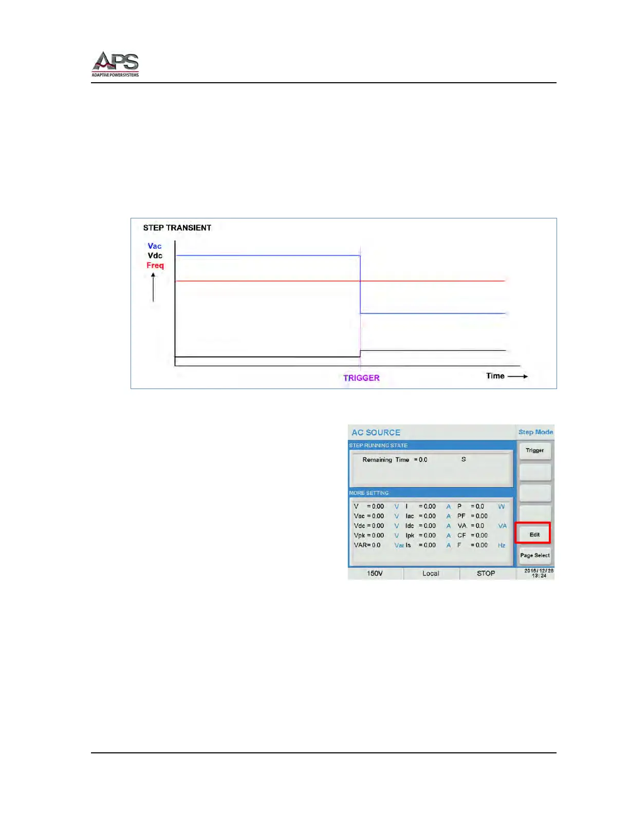
These values can be entered using the Step Mode screen. Press the [Edit] soft key to enter
edit mode.