R5906848 /04 DP2K SLP Series146
Caution: Maximum ten (10) seconds are allowed of minimum light output on a non-adjusted
Integration Rod. Otherwise, the DMD's may be damaged.
4. Activate the light source and zoom the projector lens in or out until the projected image is focused.
Note: Dialog windows must be displayed sharp instead of blurry. This is independent of the focus of
the light beam.
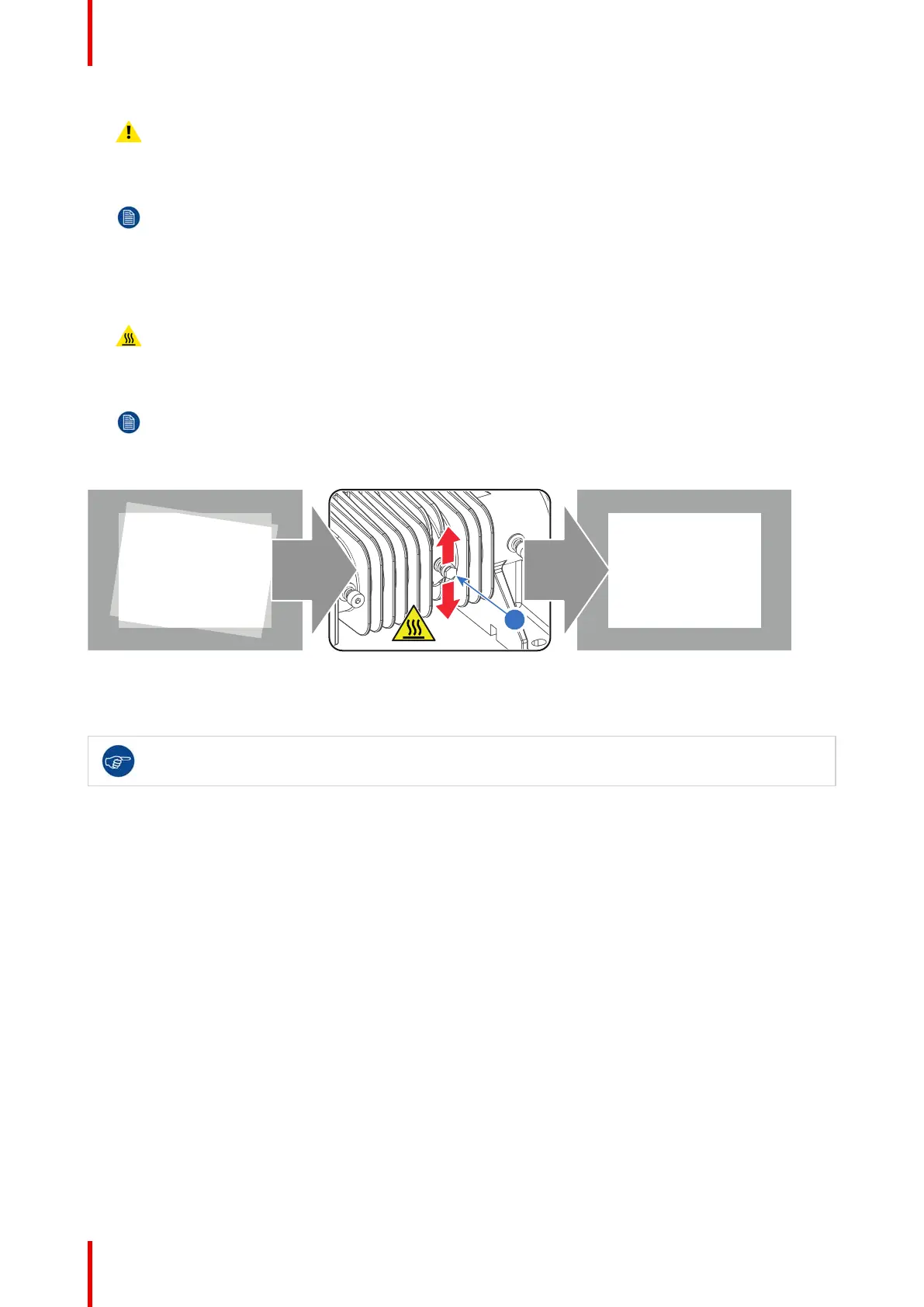
5. Gently move the adjustment screw (reference 1 Image 11-9) of the Integration Rod UP or DOWN until the
projected light beam matches the projected outline of the DMD's (ROTATION). Use a 5.5 mm nut driver as an
extension bar of the adjustment screw. This allows a more precise adjustment.
Warning: The adjustment screw of the Integration Rod is hot. To prevent burn injuries use 5.5mm nut
driver for moving the Integration Rod.
Note: No spots in the projected image may move along with the movements of the Integration Rod.
Spots which move with the movements of the Integration Rod indicates that the exit side of the
Integration Rod is contaminated with dust.
If this is the case, remove the Notch Filter and try to blow away the dust.
If this doesn't help replace the Integration Rod.
Image 11-9
6. Fasten the adjustment screw (reference 1 Image 11-9) which you released in step 1. Use a 5.5 mm Allen
wrench.
It's recommended to check the Light Pipe focus (Lens No1) and the Light Pipe zoom (Lens No3)
after adjusting the Integration Rod.
Integration Rod

 Loading...


