R5906848 /04 DP2K SLP Series 241
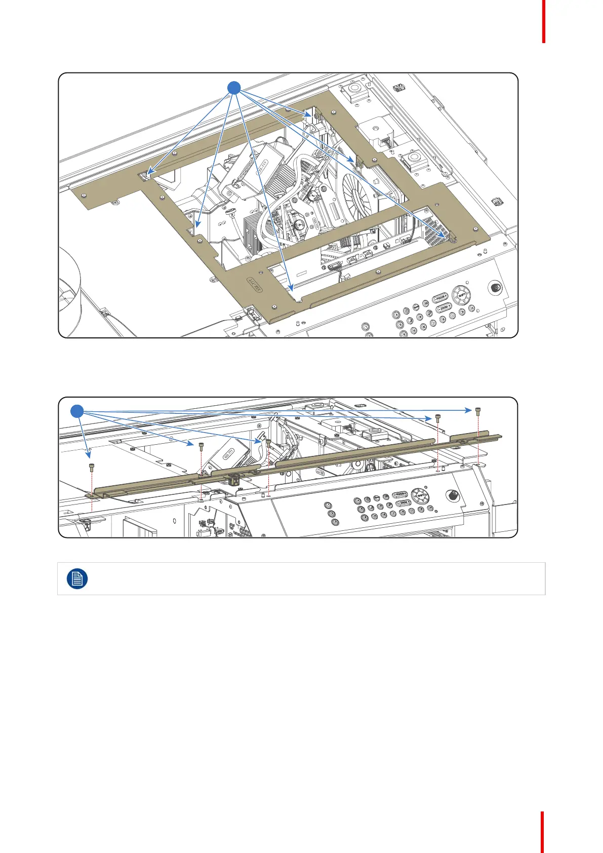
Image 18-50
6. Install the rail on the top of the projector as illustrated. Use a 3mm Allen wrench to fasten the 5 screws
(reference 4 Image 18-51).
Image 18-51
After the Card Cage is installed the electrical connections between Card Cage and other projector
components has to be established. See procedure “Connecting the Card Cage wires”, page 241.
18.21 Connecting the Card Cage wires
Connecting the Card Cage wires
1. Connect the three wires (reference 9, 10 and 11 Image 18-52) with the rear-base side of the Signal Backplane.
• Reference 11 - two pins plug with orange wires from security switch.
• Reference 10 - two pins plug with yellow wires from security switch.
• Reference 9 - ten pins plug with 8 wires from 3D-module.
2. Connect the four orange wires of the Light Processor and the brown wire with the Signal Distribution board as
illustrated in Image 18-52.
• Reference 8 - two pins plug with orange wires and red cable tie from temperature sensor red channel.
• Reference 7 - two pins plug with orange wires and green cable tie from temperature sensor green channel.
Card Cage

 Loading...


