R5906848 /04 DP2K SLP Series242
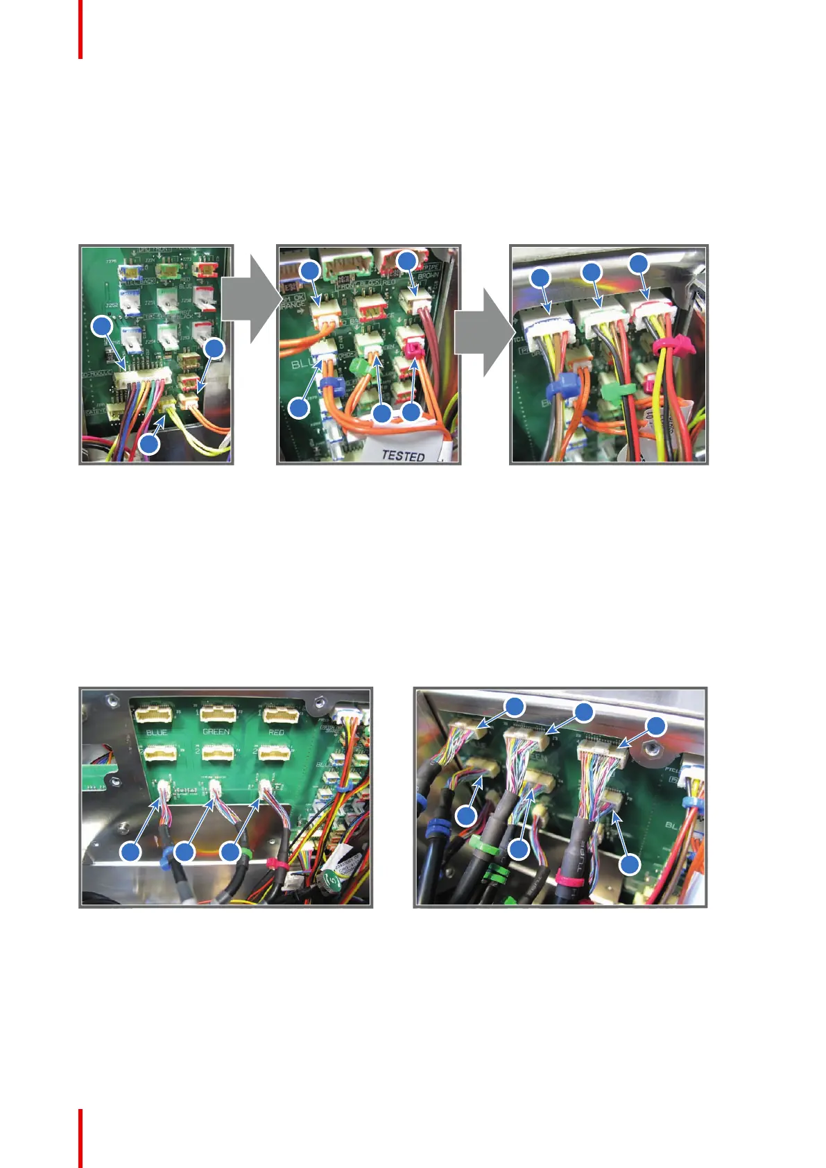
• Reference 6 - two pins plug with orange wires and blue cable tie from temperature sensor blue channel.
• Reference 5 - two pins plug with orange wires from Prism Sensor.
• Reference 4 - two pins plug with brown wires from Temperature Sensor Light Pipe.
3. Connect the three wires (reference 1, 2 and 3 Image 18-52) of the DMD fans with the Signal Backplane.
• Reference 3 - four pins plug with red cable tie from fan DMD Red channel.
• Reference 2 - four pins plug with green cable tie from fan DMD Green channel.
• Reference 1 - four pins plug with blue cable tie from fan DMD Blue channel.
Image 18-52
4. Connect the nine RGB connectors (reference 1 to 9 of Image 18-53) with the Signal Backplane as illustrated.
• Reference 1 - small connector with blue cable tie.
• Reference 2 - small connector with green cable tie.
• Reference 3 - small connector with red cable tie.
• Reference 4 - connector with two blue cable ties.
• Reference 5 - connector with two green cable ties.
• Reference 6 - connector with two red cable ties.
• Reference 7 - connector with one blue cable tie.
• Reference 8 - connector with one green cable tie.
• Reference 9 - connector with one red cable tie.
Image 18-53
5. Connect the CLO wire (reference 10 ) with the Signal Backplane.
Card Cage

 Loading...


