R5906848 /04 DP2K SLP Series 243
Image 18-54
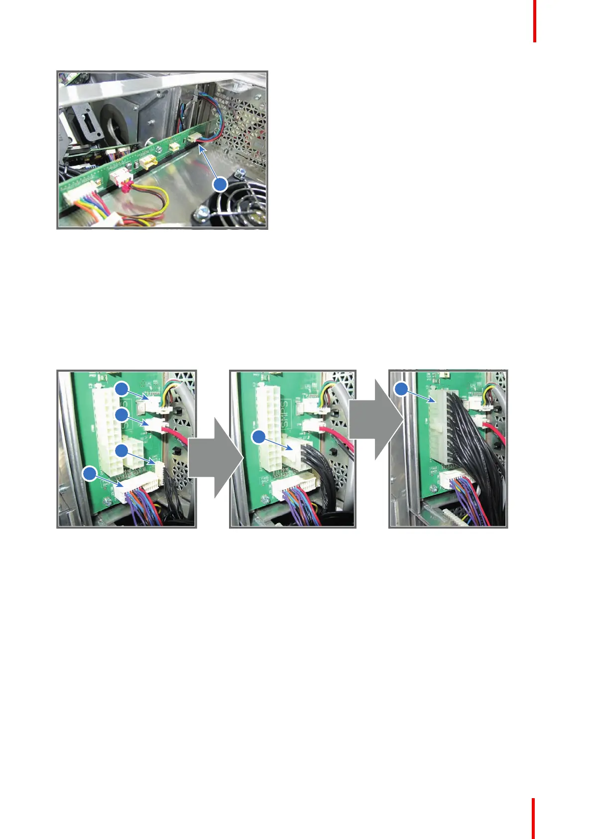
6. Connect the four wires (reference 1, 2, 3 and 4 Image 18-55) with Signal Backplane at the lower left side of the
Card Cage as illustrated:
• Reference 1 - SMPS CTRL plug (10 pins, black wires)
• Reference 2 - FANS BACK plug (multi pins, different colored wires)
• Reference 3 - Power plug RELAY (2 pins, red/black wire)
• Reference 4 - ULCB plug (8 pins, different colored wires)
7. Connect the two SMPS plugs with black wires with the Signal Backplane. First insert the small plug (reference
5 Image 18-55) then insert the larger plug (reference 6 Image 18-55).
Image 18-55
8. Connect the three wires (reference 7, 8 and 9Image 18-55) with Signal Backplane at the upper left side of the
Card Cage as illustrated:
• Reference 7 - TAIL LIGHT plug (4 pins, different colored wires)
• Reference 8 - LIGHT SOURCE SWITCH plug (2 pins, red wires)
• Reference 9 - TEMP OUTLET plug (2 pins, yellow wires)
Card Cage

 Loading...


