R5906848 /04 DP2K SLP Series244
Image 18-56
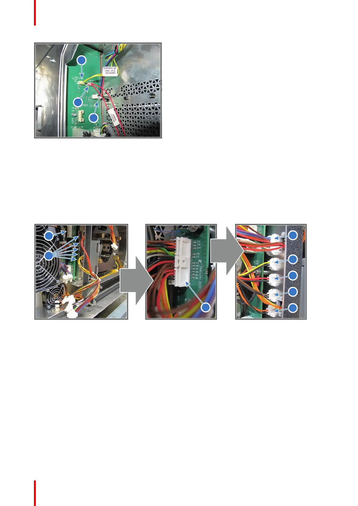
9. Connect the big wire plug (reference 3 Image 18-57) of the lens motors with the Signal Backplane.
10. Engage the five wire sockets (reference 5, 6, 7, 8 and 9 Image 18-57) into the projector chassis as illustrated.
The sockets must be ordered from top to bottom as follows:
• Reference 5 - Lens wires (zoom & focus) (orange wires).
• Reference 6 - Horizontal-Left end loop wires (yellow/black).
• Reference 7 - Vertical-Top end loop wires (red/black).
• Reference 8 - Vertical-Bottom end loop wires (brown/black).
• Reference 9 - Horizontal-Right end loop wires (orange/black).
Image 18-57
11. Connect the 5 wires (reference 5, 6, 7, 8 and 9 Image 18-58) with the sockets in the chassis at the left side
from the Lens Holder as illustrated. The plugs must be ordered from top to bottom as follows:
• Reference 5 - Lens wires (zoom & focus) (orange wires).
• Reference 6 - Horizontal-Left end loop wires (yellow/black).
• Reference 7 - Vertical-Top end loop wires (red/black).
• Reference 8 - Vertical-Bottom end loop wires (brown/black).
• Reference 9 - Horizontal-Right end loop wires (orange/black).
Card Cage

 Loading...


