R5906848 /04 DP2K SLP Series 231
Image 18-29
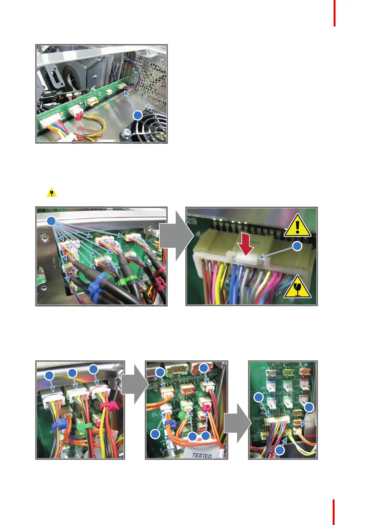
6. Disconnect the nine RGB connectors (reference 3 Image 18-30) from the Signal Distribution board. Push the
little tab (reference 4 Image 18-30) down with your fingernail and then pull the connector gently out of its
socket. The connector should come out easily from its socket.
Caution: Always push-in the little tab of the connector to remove the connector from its socket.
Neglecting this will result in irreversible damage of the socket.
Image 18-30
7. Disconnect all other wires from the rear side of the Signal Backplane.
• Start with the three wires at the top (reference 1, 2 & 3),
• then the brown wire and the four orange wires in the middle (reference 4, 5, 6, 7 and 8),
• and finally the three remaining wires at the bottom (reference 9, 10 & 11).
Image 18-31
Card Cage

 Loading...


